


6
6. User System Connector Pin Assignment
■ Pin assignment
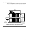
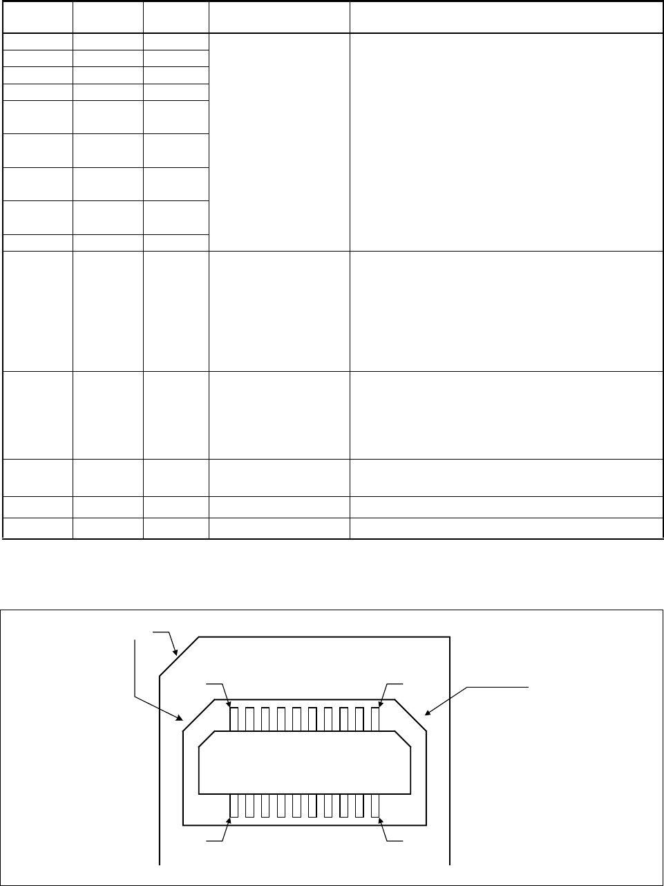
Table 1 User System Connector Pin Assignment
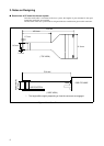
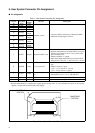
Figure 5 User System Connector Form
PIN No. PIN name
Input /
output
Function Description
20 ICLK Input
Emulator control
• Connects with the same name of Evaluation MCU.
• Maximum wiring length is 50 mm.
18 ICS[0] Input
17 ICS[1] Input
16 ICS[2] Input
14 ICD[0]
Input and
output
13 ICD[1]
Input and
output
12 ICD[2]
Input and
output
11 ICD[3]
Input and
output
10 BREAK Output
7 INITX Output Evaluation MCU reset
• Connects with the reset pin of Evaluation MCU.
• Separate wiring between evaluation MCU reset pins-
from the reset output circuit on a user system at the-
time of emulator use.
• Effective with the "L" output.
• Open drain output.10 kΩ pull-up resistance built-in
using the UV
CC pin.(VOL = +0.4 V max, IOL = 12 mA)
6 xRSTIN Input User system reset
• Connects with the reset output circuit of a user sys-
tem.
• Effective in the "L" input.
(V
IH = +1.7 V min, IIH = −10 µA)
(V
IL = +0.8 V max, IIL = 10 µA)
4
UVcc*
Input
User system power sup-
ply
• Connects with the external I/O power supply of Eval-
uation MCU.(0 V to +5.5 V / 100 mA less)
9,15,19 GND - GND
• Connects with the V
SS pin (0 V) of Evaluation MCU.
1,2,3,5,8 N.C. - -
• Since it is intact, it opens.
*:When Evaluation MCU is a single power supply, please connect with a V
CC pin, and in the case of two or more power
supplies, connect with an external I/O power supply.
CAMFERING
PORTION
CAMFERING
PORTION
1PIN
2 PIN
19 PIN
20 PIN