


Part # 4522970 Rev 1 (10/28/09)Page 6
INSTALLATION Continued
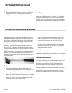
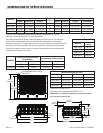
Positioning and Setup
Some form of mechanical assistance will be required to
position these broilers, as the smallest weighs 338 lbs
(153 kg) and the larger sizes weigh 620 lbs (281kg). A pallet
or lift jack will also make leveling easier, as these units are
designed to sit ush on a counter, do not have adjustable
legs or feet, and leveling is with shims and repeated tting.
Inside the unit, the char-broilers use cast tubular burners
with cast iron radiants, which are secured to the burner
hangers to stop vibration and damage during shipping Once
free, double-check that the burners are positioned squarely
in the notches of the back burner holder. If they are out of
position, the burner will not work properly.
Air Supply and Ventilation
The area around the appliance must be kept clear to avoid
any obstruction to the ow of combustion and ventilation
air, as well as, for ease of maintenance and service.
Means must be provided for any commercial, heavy-duty
cooking appliance to exhaust combustion waste products
to the outside of the building. This is doubly important for
open grate broilers, since the design promotes grease and fat
dripping through onto hot radiants sending smoke back up
onto the product as seasoning. This smoke then continues
either up to the ceiling or to an exhaust hood. Garland
Char-Broilers must be under a vent hood! Filters and drip
troughs should be part of any industrial hood, but consult
local codes before constructing and installing a hood.
Air movement should be checked during installation,
strong exhaust fans in the hood or in the overall system can
produce a vacuum in the room and/or cause air drafts. Either
of which can interfere with the burner performance and be
dicult to diagnose. If burner problems persist, make-up air
openings or baes may have to be provided in the room.
Any adjustments to air movement should be performed or
inspected by a qualied technical installer. Maintain and do
not block the appliances designed air openings.
Gas Connection
NOTE: The gas supply (service) line must be the same size or
greater than the inlet line of the appliance. Garland Char-
Broilers use a 3/4” NPT inlet. Sealant on all pipe joints must be
resistive to LP gas.
The appliance and its individual shut-o valve must be
disconnected from the gas supply piping system during any
pressure testing of that system at test pressures in excess of
1/2 psi (3.45 kPa).
The appliance must be isolated from the gas supply piping
system by closing its individual manual shut-o valve during
any pressure testing of the gas supply piping system at test
pressures equal to or less than 1/2 psi (3.45 kPa).
Manual Shut-O Valve
The Manual Shut-O Valve is supplied by the installer, it must
be installed in the gas service line ahead of the appliance
and regulator in the gas stream and in a position where it can
be reached quickly in the event of an emergency.
Pressure Regulator
All heavy-duty, commercial cooking equipment must have
a pressure regulator in the incoming service line for safe and
ecient operation, since service pressure may uctuate with
local demand. The manual shut-o valve is normally supplied
by the installer, but pressure regulators are shipped from
Garland with every Char-Broiler.
Regulators are pre-set at the factory for 4”WC (natural gas)
or 10”WC (propane) according to the customer’s ordering
instructions. Adjust regulator to manifold operating pressure
as per rating plate.
Prior to connecting the regulator, check the incoming line
pressure, as these regulators can withstand a maximum
pressure of 1/2 psi (14” WC). If the Line pressure is beyond
this limit, a step-down regulator will be required. Double-
check the arrow forged onto the bottom of the regulator
body which shows gas ow directions; it should point
downstream to the appliance. The red air-vent cap is part of
the regulator and should not be removed unless local codes
require external venting.
Regulators can be adjusted in the eld, but it is
recommended that they not be tampered with unless that
part is known to be out of adjustment or serious pressure
uctuations are found to exist and can be solved no other
way. Any adjustments to regulators must be made by
qualied service personnel with the proper test equipment.
If a vent line from the gas appliance pressure regulator is
used, it should be installed to the outdoors in accordance
with local codes or, in the absence of local codes, with the
National Fuel code, ANSI Z223.1, Natural Gas Installation
Code, CAN/CGA-B149.1 or the Propane Installation Code,
CAN/CGA-B149.2, as applicable.
WARNING: Failure to install a pressure regulator will void the
equipment warranty!