


35
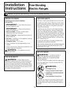
Installation Instructions
PREPARE TO INSTALL THE RANGE
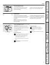
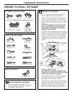
TOOLS YOU WILL NEED
MATERIALS YOU MAY NEED
Anchor SleevesLag BoltsTin Snips
(For Anti-Tip Bracket Mounted on Concrete Floors Only)
3-Wire Cord
4‘ Long
4-Wire Cord OR
4‘ Long
(UL Approved 40 AMP)
Adjustable Wrench
Level
1/4” Nut Driver
Phillips Screwdriver
Drill with 1/8” Bit
Pencil
Safety Glasses
Tape Measure
Pliers
Flat-blade Screwdriver
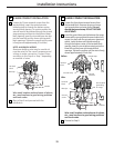
PARTS INCLUDED
Anti-Tip Bracket Kit
REMOVE SHIPPING MATERIALS
Remove packaging materials. Failure to
remove packaging materials could result
in damage to the appliance.
1
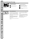
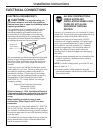
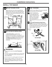
PREPARE THE OPENING
Allow 1
1
⁄2″ spacing from the range to adjacent
vertical walls above the cooktop surface.
Allow 30″ minimum clearance between the
surface units and the bottom of unprotected
wood or metal top cabinet, and 15″ minimum
between the countertop and adjacent cabinet
bottom.
EXCEPTION: Installation of a listed microwave
oven or cooking appliance over the cooktop
shall conform to the installation instructions
packed with that appliance.
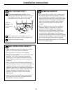
If cabinet storage is installed, reduce the risk by
installing a range hood that projects horizontally
a min. of 5″ beyond the bottom of the cabinets.
Make sure the wall covering, countertops and
cabinets around the range can withstand heat
generated by the range, oven or cooktop up
to 200°F.
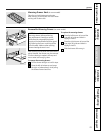
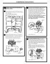
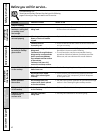
Flooring under the range
Your range, like many other household items,
is heavy and can settle into soft floor coverings
such as cushioned vinyl or carpeting.
When moving the range on this type of flooring,
it should be installed on a 1/4″ thick sheet of
plywood (or similar material) as follows:
When the floor covering ends at the front of the
range, the area that the range will rest on should
be built up with plywood to the same level or
higher than the floor covering. This will allow the
range to be moved for cleaning or servicing.
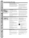
2
Cord
Wall
Floor
7″
5″
C of range
L
Outlet
box
Hood
Wall
Not less than
the width of the
range
5″ Min.
30″
Min.
15″
Min.
1
1
⁄2″
Min.
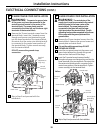
Locate the outlet box within
either shaded area.
2
1
⁄4″
7
1
⁄2″
7
1
⁄2″
3
1
⁄2″
Install the
outlet box
on either
side of the C
L
Squeeze Connector
(For Conduit
Installations Only)