


39
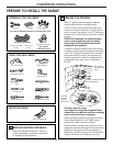
Installation Instructions
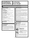
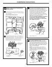
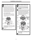
3-WIRE CONDUIT INSTALLATION
Loosen the 3 lower terminal screws from the
terminal block. Insert the center bare wire
(white/neutral) tip through the bottom center
terminal block opening. On certain models, the
wire will need to be inserted through the ground
strap opening and then into the bottom center
block opening. Insert the two side bare wire tips
into the lower left and the lower right terminal
block openings. Tighten the screws until the wire
is firmly secure (approximately 20 inch-lbs.).
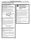
NOTE: ALUMINUM WIRING:
Aluminum building wire may be used but it
must be rated for the correct amperage and
voltage to make connection. Connect wires
according to this Step 6 or Step 7 depending
on number of wires.
Wire used, location and enclosure of splices,
etc., must conform to good wiring practices
and local codes.
Skip to Step 8 and proceed with the
installation.
B
A
6
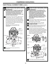
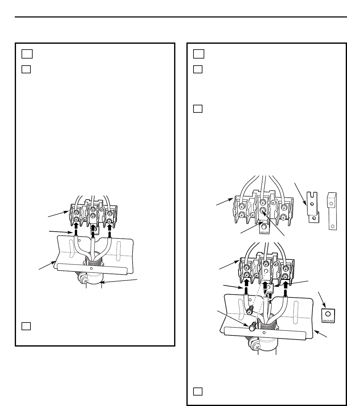
4-WIRE CONDUIT INSTALLATION
Loosen the three lower terminal screws from
the terminal block. Remove the ground screw
and ground plate and retain them. Cut and
discard the ground strap. DO NOT DISCARD
ANY SCREWS.
Insert the ground bare wire tip between the range
frame and the ground plate (removed earlier) and
secure it in place with the ground screw (removed
earlier). Insert the bare wire (white/neutral) tip
through the bottom center of the terminal block
opening. Insert the two side bare wire tips into the
lower left and the lower right terminal block
openings. Tighten the screws until the wire is firmly
secure (approximately 20 inch-lbs.).
Wire used, location and enclosure of splices,
etc., must conform to good wiring practices
and local codes.
Proceed to Step 8.
C
B
A
7
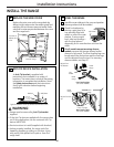
Before
Terminal
block
Ground strap
After
Terminal
block
Ground plate
(grounding
to range)
Bracket
Neutral
terminal
Wire tips
Wire tips
Terminal
block
Conduit
Bracket
Ground
screw
Ground strap
or