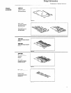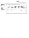
Design Information
Step
Preparing
for
Installation
.
Component Cooking Surfaces
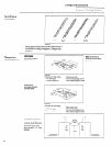
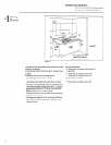
13”
t~
Max.
I II
d
One or
30”
Min.
A ~
●*1” Min.
●2” Min.
to Wall
●1” Min
36”
to Front
to Wall
Edge
●Gas in to side to side orientation
A
requres 2“ min. to rear wall,
●* Gas requires 2“ min. to side wall
●Refer to Cutout
Information
.---—.“ .
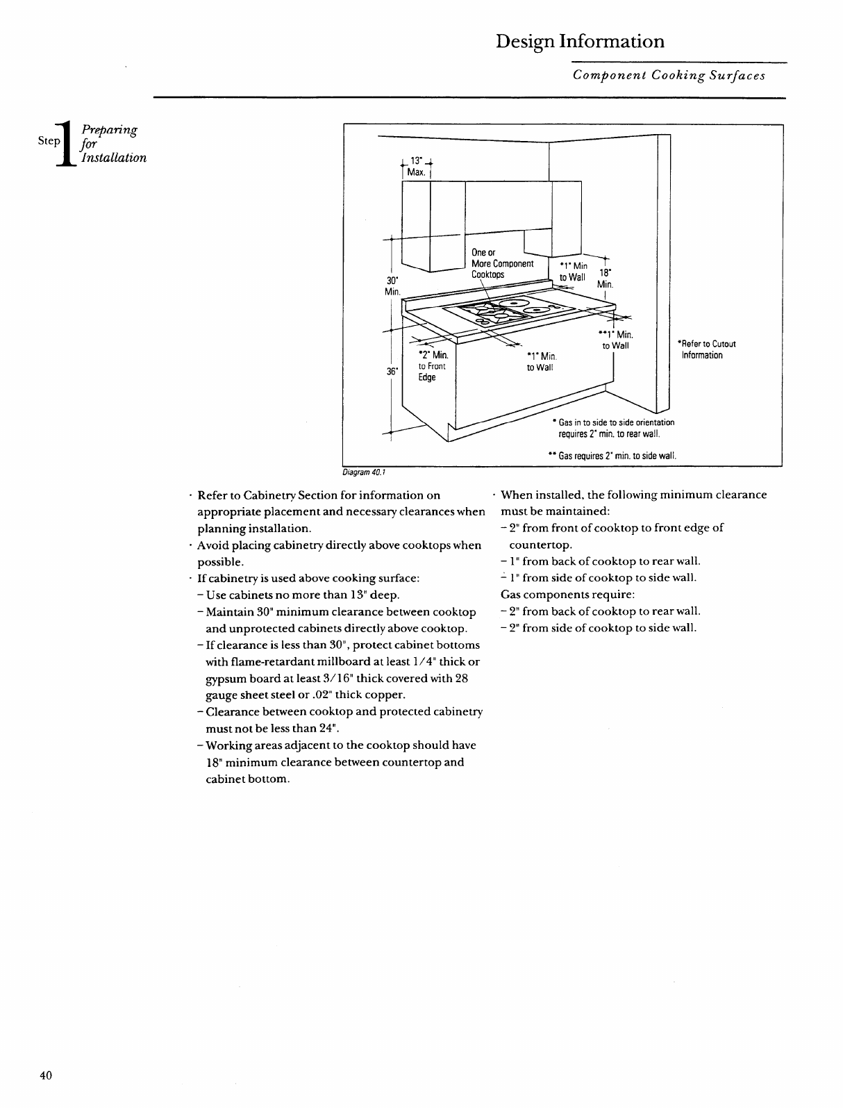
c Refer to Cabinet~ Section for information on
appropriate placement and necessary clearances when
planning installation.
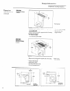
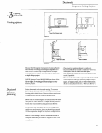
“ Avoid placing cabinetry directly above cooktops when
possible.
- If cabinetry is used above cooking surface:
– Use cabinets no more than 13“ deep.
– Maintain 30” minimum clearance between cooktop
and unprotected cabinets directly above cooktop.
– If clearance is less than 30”, protect cabinet bottoms
with flame-retardant millboard at least 1/4” thick or
~~psum board at least 3/ 16“ thick covered with 28
gauge sheet steel or .02” thick copper.
- Clearance between cooktop and protected cabinetry
must not be less than 24”.
– Working areas adjacent to the cooktop should have
18“ minimum clearance between countertop and
cabinet bottom.
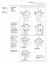
. When installed, the following minimum clearance
must be maintained:
- 2“ from front of cooktop to front edge of
countertop.
– 1” from back of cooktop to rear wall.
-1” from side of cooktop to side wall.
Gas components require:
– 2“ from back of cooktop to rear wall.
– 2“ from side of cooktop to side wall.
40


