


SETUP PROCEDURE
MOUNTING DISPENSE VALVE
Mounting holes are drilled through the valve body. The valve may be tilted to a maximum of 60 degrees
from the vertical depending on the application.
AIR CONTROLLER
Operation of the Model 710 Dispense Valve requires a controller that can provide the following:
A minimum of 0.5 SCFM (2.3 cm
3
) of dry unlubricated air at a minimum pressure of 70 psi (4.8 bar) and a
maximum of 100 psi (6.9 bar).
Time delay capability to allow the valve to cycle.
Independent air pressure regulators for material supply and valve operation.
“Purge capability”
which is the ability for the operator to pass or not pass air to the Open port on the dispense
valve.
For semiautomatic or automatic applications, a foot switch or other control to cycle the valve.
Connection for .16”ID x .25” OD (6.35mm) pressure tubing for use between the dispense valve and
controller.
Connection for a .16”ID x .25” OD (6.35mm) pressure tubing for use between the controller and syringe.
OPERATING PROCEDURES
DRY SYSTEM CHECKOUT
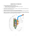
This is an initial checkout to determine if the setup has been properly completed. The dry checkout is
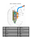
conducted without any material in the system. Refer to the illustrations above or below.
1. Turn on the controller and the air supply.
2. Set the air pressure to 70 psi (4.8 bar) on the system pressure gauge.
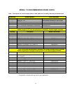
3. In the normal “ready” state the Piston (4) is seated in the Needle Seat (1), sealing the dispense
valve. For this test, loosen the Nut (2) and remove the Needle Block (23) and Needle Seat (1) so
that you can visually verify that the Piston (4) rises inside the Valve Sleeve (3).
4. Momentarily press the dispense valve cycling control switch.
5. The controller applies air to the Open port of the dispense valve, the Piston (4) lifts. After the time
delay the controller applies air to the Close port causing the Piston (4) to move down. Visually
verify the piston movement. When this happens, the system is correctly installed.
6. Reinstall the Needle Block (23) and Needle Seat (1) with the Nut (2). Anytime the Needle Seat (1)
is replaced, you must loosen the Hex Nut (20) and tighten the Adjustment Screw (21) into the Valve
Body (5) until it seats. Then back off the Adjustment Screw (21) approximately 2 turns and tighten
the Hex Nut (20). This step is required for proper adjustment of the Piston (4).
5
If there are any problems in getting started, refer to the Troubleshooting
section or call Technical Service at (330) 494-1313.