


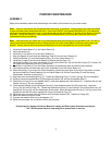


PERIODIC MAINTENANCE
ASSEMBLY
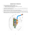
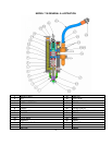
Refer to the illustration above and the drawings at the back of this manual for your exact model.
Note: Clean all valve parts with an appropriate solvent prior to assembly. Always install new, lightly lubricated
o-rings and seals when assembling the valve. Use Krytox 203GPL (part number 84/0200-K3/11) for lubricating
valve parts including seals and o-rings. Lubricate the bore of the Valve Body (3) and the Valve Sleeve (3) before
assembly. Check the Piston (4), Valve Sleeve (3) and Needle Seat (1) for wear and if they are worn secure
replacements before proceeding.
Note: Use caution as you install new U-cup and Posipak seals so that they are not pinched or torn. Do this by
making sure they are lubricated, and by tucking the lips of the seal inward before uniformly pushing them into
position. Always consult the illustrations and drawings to be sure that seals face the correct direction.
1. Install the Posipak Seals (7) in the Valve Sleeve (3).
2. Insert the Spacer (8).
3. Install the U-cup Seals (10) in the Valve Sleeve (3).
4. Align the Spacer (8) and insert the Retaining Tube (9) into the Valve Sleeve (3).
5. Install the Washer (11) and the Retaining Ring (12) in the Valve Sleeve (3).
6. Install the O-rings (6) on the Valve Sleeve (3) and on the End Cap (14).
7. Install the End Cap (14) in the Valve Body (5). Secure the End Cap (14) with the Set Screw (27). Caution: Do
not install the Adjustment Screw (21) at this time.
8. Install the U-cup Seals (16) on the Piston Assembly (4) positioning them as noted in the illustration.
9. Lubricate the piston rod and insert the Piston Assembly (4) into the Valve Sleeve (3).
10. Place the Spring (13) on top of the Piston Assembly (4) and using the boss on the top of the piston to center
the spring insert the Piston Assembly (4) and Valve Sleeve (3) into the Valve Body (5) until the spring
compresses. Hold this in place firmly.
11. Align and insert the Retaining Plug (17). Tighten the Retaining Plug (17) until it is snug. Do not overtighten.
12. Carefully install the Needle Block (23) through the Gasket (24) and into the Needle Seat (1).
13. Position the O-ring (18) on the Needle Seat (1) and place against the Valve Sleeve (3). Install the Nut (2) and
tighten until snug. Do not overtighten.
14. Lubricate the threads of the Adjustment Screw (21) and thread the Hex Nut (20) onto it fully. Insert the
O-ring (19) into the End Cap (14). Thread the Adjustment Screw (21) and Hex Nut (20) into the End Cap (14)
through the O-ring (19) until the Adjustment Screw stops. Back the Adjustment Screw (21) off two turns, then
tighten the Hex Nut (20) down against the O-ring (19) and End Cap (14).
15. Install the open port and close port Elbows (25) and their Gaskets (24). Install the Tubing (29).
16. Mount the valve to its point of use.
17. Connect the material inlet line to the Adapter (15).
18. Attach the air supply line connectors (28) to the controller.
Perform the Dry System Checkout, Material Loading and Wet System Checkout procedures.
The 710S Dispense Valve is now ready to be placed back in service.
9