


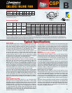
H1
BLK
SWITCH BOX
SWITCH
115 V MOTOR
277 V SUPPLY
277V TO 115V TRANS.
750 VA
H2 H3
RED
X1 X2
RED
BLK BLK
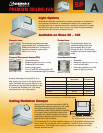
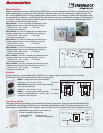
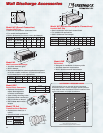
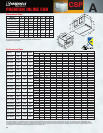
Grille Motion Detectors
are available on models up
through size SP-A390 and
SP-B200.
• Rated for 115v
• UL Listed
Model MDW
For use on fan or lights.
Available shipped loose.
• Rated for 115v
• UL Listed
• Requires 2x4 handy box
Grille Mount
Wall Mount
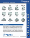
Model T-2.0 - UL Listed
• Rated for 230/277v to 115, 2 Amps
Model T-4.3 - UL Listed
• Rated for 230/277v to 115, 4.3 Amps
Model T-6.5 - UL Listed
• Rated for 230/277v to 115, 6.5 Amps
Model T-8.6 - UL Listed
• Rated for 230/277v to 115, 8.6 Amps
Gnd.
Hot
Black
Green
Red
Load
(12.5 Amps Max.)
Neutral
Black
Red
Black
White
White
Hot
Neutral
Ground
Motion Sensor
Fan Motor and/or
Light
Green
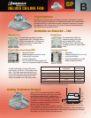
Motion Detectors
Motion detectors may be used with Models SP and CSP fans, or fan and light combinations. Motion detectors
use a passive infrared motion detector that will automatically turn on the fan when a change in temperature is
sensed. They have a viewing area of 180 degrees, however they must be placed in the line-of-sight. They also
have an adjustable time delay shutoff setting of 1 to 20 minutes.
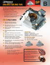
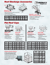
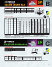
Ceiling Radiation Dampers
The Greenheck SP-A and SP-B ceiling
radiation dampers are UL Classified, rated
at three to four hours fire resistance, and
is available on all SP-A and SP-B fans and
fan/light combinations. This design saves
space by allowing the damper to mount
directly beneath the fan.
All dimensions shown in inches.
Add an “L” to all CRD models if fan & light combo is used.
®
AccessoriesAccessories
13
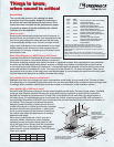
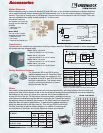
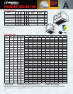
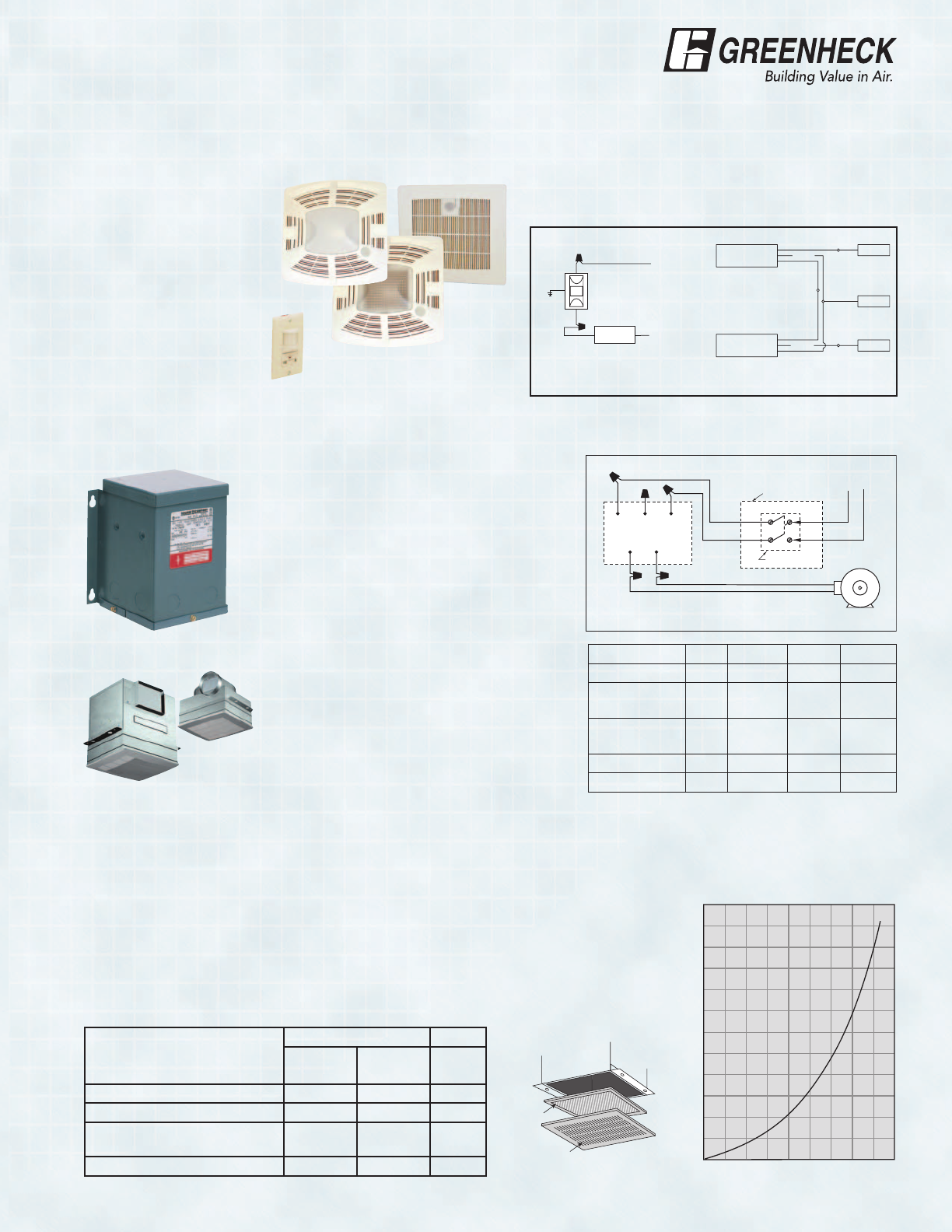
Filters
Fans used in most applications, even where air is not excessively dirty, will collect airborne dirt on wheels and
motors over time. Accumulations of dirt on the fan wheel will sharply reduce performance and cause imbalance.
Dirt buildup on the motor can cause it to overheat. All of these conditions will
shorten the life of the fan. To help reduce this accumulation, washable aluminum
mesh filters are available to trap dirt before it enters the fan. These filters should
be regularly cleaned to maintain performance. The Filter Loss Chart shows the
effect the filter will have on performance. To determine the added resistance,
divide the desired cfm by the filter area (ft
2
). This will give FPM. Use this with
the filter loss chart to get the added resistance. In addition to reducing dirt
accumulations on the motor and wheel, filters also reduce sound levels.
Mesh
Filter
SP
Grille
.24
.22
.20
.18
.16
Resistance in w.c.
.14
.12
.10
.08
.06
.04
.02
.00
Velocity FPM x 100
0123456789
Transformers
Transformers are available for applications requiring voltage reduction. Selection is based on motor amperage.
All transformers are shipped loose.
All dimensions shown in inches. *Aluminium or Stainless Steel Grille.
FILTER LOSS CHART
SP Model CRD Length Width Height
A50 - A190 310 13
1
/2 11
1
/8 3
B50 - B200
A200 - A390
320 14
3
/8 12
1
/4 3
A410 - A510
A710 - A780
350 18
7
/16 14
15
/16 3
A - 700 700 24
3
/16 12
1
/4 3
A900 - A1550 360 24
3
/16 14
15
/16 3
SP Model
Filter Model Filter
Designer
Grill
*Metal
Grille
Area
(ft
2
)
SP-A50 - A190 F-200 F-210 .620
SP-B50 - B200, A200 - A390 F-200 F-220 .785
SP-A410 - A510
SP-A710 - A780
NA F-250 1.319
SP-A900 - A155 NA F-260 1.797