


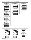
16
Model GGH2O
®
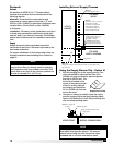
Plumbing
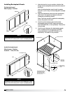
1. Connect the inlet and outlet piping on the
recirculation pump to the respective piping in the
cabinet via the threaded 1 in. unions.
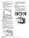
2. Bring the inlet water piping to the connection
located on the top of the hood and connect to the
threaded connection on the 3/4 in. solenoid valve.
A ball valve needs to be placed in the connection
line before the 3/4 in. solenoid valve. Depending
on water pressure, the inlet valve might need to
be closed slightly to reduce water pressure. Water
temperature should be 140°F.
3. Bring the drain piping connection to the 1 in.
solenoid valve in the control cabinet and connect
to the threaded connection. This is a pressurized
drain system and needs a properly sized drain to
accommodate the pressurized drain water.
NOTE
As the suggested detergent is non-caustic and
biodegradable, waste water from the hood can be
drained in any typical grease trap.
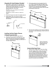
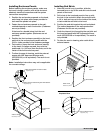
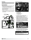
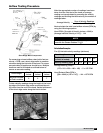
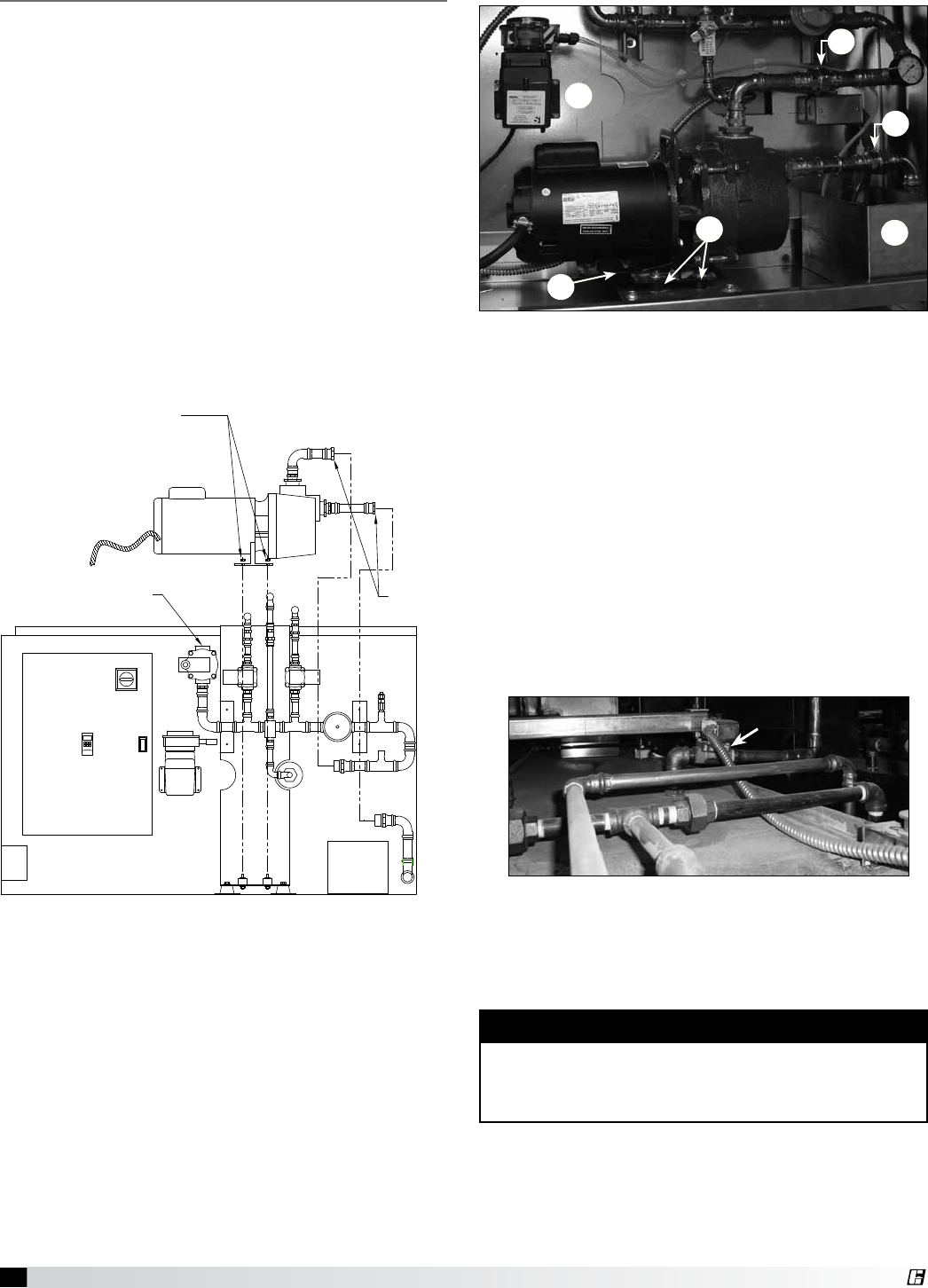
A. One-inch unions
B. Detergent tank
C. Mounting plate
D. Isolators (qty of four)
E. Detergent pump
Position pump on
(4) isolators and attach
using provided nuts.
Field
connect
1-inch
unions
1-inch female NPT
Connect to drain
Connect to control
cabinet per
Wiring Diagram
in panel
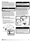
Once the hood is hung, the recirculation pump and
detergent tank (both shipped loose) must be installed
in the controls cabinet.
Pump Installation
• Remove bolts from pump mounting plate in cabinet.
• Place the pump on the isolators located on the
mounting plate with the bolts removed.
• Secure the pump to the mounting plate with the four
previously removed bolts.
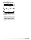
• Wire pump motor to the control cabinet per wiring
diagram on the cabinet.
• The wires to power the motor are already connected
to the pump motor. It only needs to be wired to the
control cabinet.
Plumbing Connections
A
A
B
C
D
E
Inlet Solenoid
Connection