


27
Model GGH2O
®
o Wash Mode
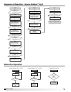
• See sequence of operations on page 20.
• If using 24 hour / 7 day timer, wash cycle will start
at scheduled time after “Fan On/Off” push button
has been pressed. (Refer to page 18 for details on
programming 24 hour / 7 day timer). If 24 hour / 7
day timer is not being used, press “Clean Hood”
push button after pressing “Fan On/Off” push
button.
• Clean hood LED indicator should be lit.
_________ Record water pressure
(Should be between 30-50 psi)
_________ Record water temperature
(Should be between 140-160°F.)
o Stop Mode
• At end of wash cycle, system returns to Fan On
for 20 minutes dry cycle.
• System resets to stop mode.
• Hood lights off. Deactivate “Hood Lights” push
button.
• All lights on face of keypad(s) should be off.
o Fire Mode
• Trip fire system microswitch or remove wire
from terminal FS or FC. (Water will not spray in
fire mode, fans will run. If wash cycle is running
during fire system trip, hood will drain and fan(s)
will run).
• System fault LED indicator should be on.
• Fan LED indicator should be lit.
o Low Detergent Mode
• Fill detergent tank with appropriate detergent.
• Low detergent LED indicator should go off.
Miscellaneous
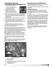
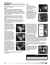
o Hood Access
• Panels should fit tightly to prevent water spraying
out.
• When front nozzles are washing, adjust ball valve
in cabinet to reduce water pressure and minimize
overspray.
o Cleaning
• Is the hood cleaning properly?
• If not, refer to troubleshooting guide on page 26.
Grease Grabber™ H
2
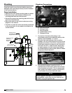
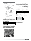
O Start-Up
Checklist
Check boxes when item has been verified and gone
over with customer.
Hook-Up
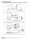
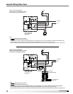
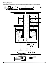
o Electrical Connected
• 120V/1 30A to terminals L1 and N for wash
controls
• 120V/1 15A to terminals L2 and N1 for hood lights
• Fans to terminals E1 and E2 (dry contact)
If using variable volume controls, Melink will also
require connection to terminals M1 and M2, Vari-
Flow will only require connection to terminals V1
and VC.
• Fire system microswitch to terminals FS and FC.
• Recirculating pump wired to cabinet terminals
RP and N.
• If keypad is shipped loose, connection completed
between keypad and cabinet with supplied cable.
If additional cable is required, consult factory for
ordering.
o Plumbing Connected
• Two 1-inch unions to recirculating pump
connected.
• Hot water supply line, 3/4-inch connection.
• Pressurized drain connection, 1-inch connection.
• Hot water supply ball valve open. Located up
stream of the inlet water solenoid valve.
o Detergent
• Suction tubing and strainer to bottom of detergent
tank.
• Low detergent sensor in bottom of detergent tank.
• Detergent tank filled with proper detergent.
o
Timer, 24 hours / 7 day
• Programmed - see instructions on page 18.
Start-Up
o Cooking Mode
• See sequence of operations on page 20.
• Hood lights on. Activate “Hood Lights” push
button.
• Hood light LED indicator should be lit.
• Fans on. Hold “Fan On/Off” push button for one-
half second.
• Fan LED indicator should be lit.
• Appliances on (gas and/or electric).
o
Stop Mode
• See sequence of operations on page 20.
• Fans off. Hold “Fan On/Off” push button for one-
half second.
• LED indicator turns off.