


Shuttle Brewers & Airpot/Shuttle Brewers Page 5
Installation (cont.)
Electric Hook-up
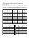
The brewer is designed to operate at the specified voltage on the nameplate with a tolerance of ± 10% for voltage
deviation. It is very important that the power line to the brewer be checked to make sure that the voltage is within
10% of the brewer’s rated voltage. Failure to provide adequate voltage, as defined above, will cause problems
with your brewer. If the power is too low, the solenoid valves may or may not work or longer recovery time will be
experienced. The brewer may be permanently damaged if the voltage is too high.
1) The electric ratings for your brewer are printed on its nameplate.
2) The brewer should be connected to its own circuit with a fused disconnect switch or a circuit breaker near the brewer.
Important: For CE units, means shall be provided to endure all pole disconnection from the supply. Such means shall be
one of the following: a supply cord fitted with plug, or a switch that is directly connected to the supply terminals and has a
contact separation of at least 3mm in each pole.
3) Attach the appropriately sized cord to the brewer with a cord grip for the 1 1/2” (3.8 cm) electric input opening.
The cord may enter through the rear or bottom on the left side of the brewer. Use an oil resistant cord such as
type SO, SOO, SAO, STOO, SEO, SJO, SJOO, SJTO, SJTOO, SJEO, HSO, HSOO, HSJO, or HSJOO.
Alternatively, flexible conduit and type THHN wires may be used. Use only copper conductors.
4) Standard connection is 1 phase 3 wire. Connect the two lines to L1 and L2 on the terminal block. If the brewer is
wired for three phase, a lug, L3, is provided on the terminal block. Neutral line should be connected to the N terminal.
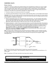
Alternately, if no neutral is available, the brewer can be wired accordingly by connecting L1 to position marked “L1”
and L2 to position marked “L2”. This will require the installer to change the connection to the transformer primary
from the white wire (120V) to the blue (208V) or orange (230,240V) connection. See below.
NOTE: This “no neutral” conversion is only applicable to units marked as 208V, 230V, or 240V. It is NOT
applicable to units marked 120/208V or 120/240V.
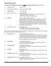
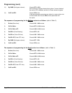
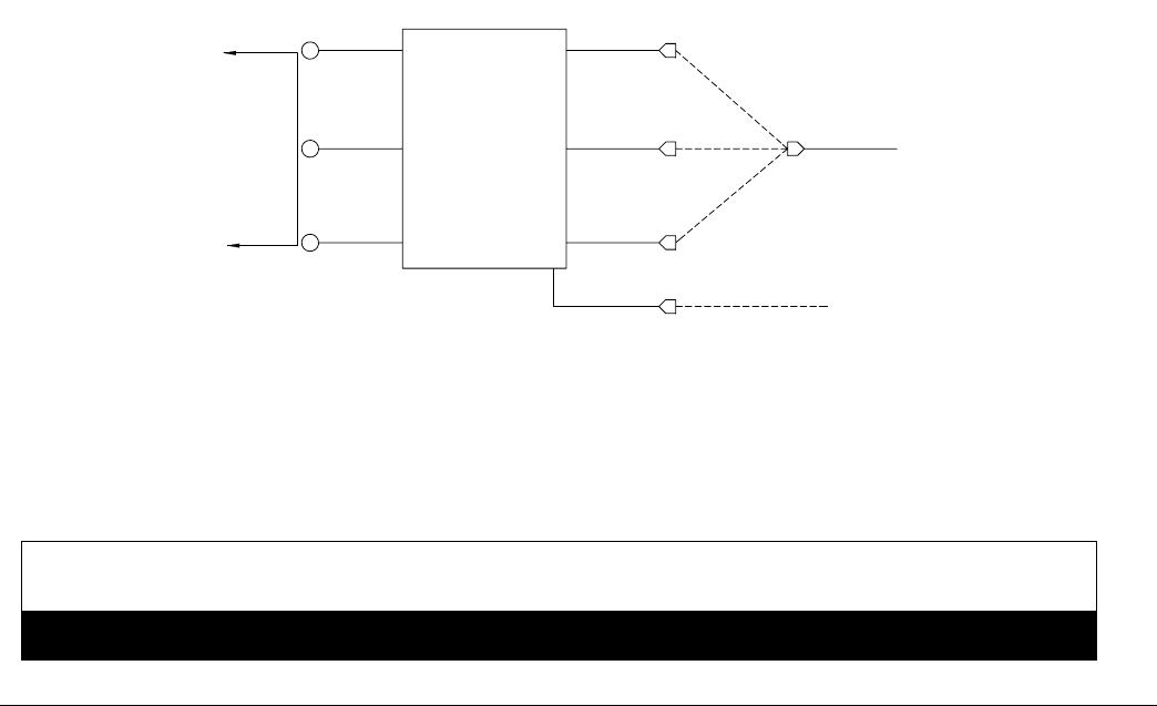
Note: The brewer utilizes a multiple tap primary transformer to convert line voltage to 24 volts for use by the controller
and some operating controls. The transformer has taps for 120V (white wire), 208V (blue wire), and 240V (orange wire)
line voltage. Be sure to connect the white wire from the terminal block to the proper tap for the supplied voltage.
See diagram below.
5) The body of the brewer must be grounded. A ground lug is provided for this purpose.
Note: If supply cord is damaged, it must be replaced by a special cord or assembly from the manufacturer, or it’s
service agent.
Note: This appliance is IP10 rated, and shall not be cleaned with a water jet.
WARNING
Never use the ground conductor as a neutral. This could cause electrocution.
ƽ
ORANGE
YELLOW
TO
CONTROLLER
YELLOW
RED
WHITE FROM
TERMINAL BLOCK
*N-120V
*L2 -208V or 230V
FROM L1BLACK
120V
WHITE
208V
BLUE
240V
TRANSFORMER