


Model 3312 Page 9
Disassembly and Cleaning (cont.)
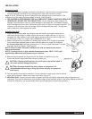
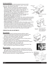
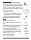
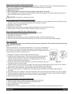
4. Remove stationary half of the shaft seal assembly from the back end of the
freezer cylinder. This is accomplished by reaching into the cylinder and pulling seal
out with your index finger. (See Figure R)
5. Slide the rotary half of the seal off the dasher shaft. Inspect both seal components
carefully for nicks or cracks. Replace seal if defective.
NOTE: To prevent leakage the surfaces of the rotary seal and the stationary seal must be
smooth with no chips or cracks.
NOTE: All units are shipped with a standard ceramic seal (Part # W0340201) unless
otherwise specified. Certain products contain coconut oil which requires a different sealing
material. For these products use the coconut oil seal (Part # W0340210). The stationary
half of the standard seal has a white polished surface. The stationary half of the coconut
oil seal has a glossy black surface.
6. Remove carb tube from bottom of hopper and remove o-rings. (See Figure S).
7. Copy disassembly procedures on other side.
8. Remove drip tray and empty contents.
9. Take all components to the cleaning area.
10. Prepare 1 gallon solution of hot tap water and a good grade of dishwashing detergent.
11. Thoroughly wash all components in a warm, mild detergent solution including the
inside of the freezing cylinder and the mix storage hopper. DO NOT WASH
COMPONENTS IN A DISHWASHER.
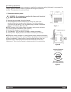
12. Use a medium sized brush to clean the bottom of the valve body and the inside of
the plunger bore with detergent solution taking care to remove only remaining
lubricant. (Figure T)
13. The exterior of the freezer should be cleaned as needed with a cloth towel.
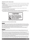
CAUTION: Coarse rags, abrasive cleaners and excessive force can
damage and/or scratch the surfaces of the freezer.
Reassembly
NOTE: Allow all parts to dry completely before reassembly.
1. Reassemble drip tray and re-install on front of unit.
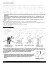
2. Wet the inner rubber lip of the rotary half of the seal and the back end of
the dasher shaft with water. Slide rotary half of assembly onto the dasher shaft,
RUBBER FIRST, with the smooth sealing surface facing the back of the dasher.
(See Figure U). Be sure the rotary half is fully seated against the shoulder of
the shaft.
3. Insert the stationary half of the seal into the ribbed rubber boot with the
polished surface facing out (forward).
4. Lightly lubricate the ribbed rubber boot of the stationary ceramic seal (taking care
not to get any lubricant on the polished surface) and insert it straight back into the
recess at the back of the freezing cylinder, RUBBER FIRST. (See Figure V)
NOTE: The stationary half of the seal must be completely dry before reassembling. If the
circular half of the seal is white, make sure that the grooved side is toward the rubber. If the
circular half is black, be sure the glossy side is facing out.
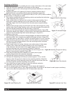
5. Reassemble the dasher assembly, as shown in Figure W. Insert the larger front
and smaller rear white plastic bearings into dasher, then slip in the stator rod.
6. Carefully and slowly guide the dasher into the freezing cylinder, taking care
not to damage the seal assembly. Turn dasher shaft until it engages the square
drive coupling. Slide the dasher back into the cylinder so that the two smooth
sealing surfaces meet. (See Figure X)
7. Inspect and lightly lubricate the large square o-ring
and refit it into the back of the valve block
assembly. Install the valve assembly on the front
studs and tighten the knobs until they are finger
tight. Do not use tools to tighten knobs.
NOTE: Failure to lightly lubricate the large o-ring can
result in product leakage.
8. Copy reassembly steps on other side.
Figure R Installing the
stationary half of seal
Figure S Carb Tube
Figure V Installing the
stationary half seal
Figure U Re-assemble rotary
half of seal as shown
!
Figure T Clean Valve Body
Figure X Seal Assembly
Figure W Dasher Assembly