


6
Caution: The water pressure is not to exceed 70 p.s.i.; water
temperature is not to exceed 110° F; conditioner cannot be
subject to freezing conditions; conditioner cannot be subject
to a negative pressure or vacuum. On installations where
there is the possibility of a negative pressure or vacuum, a
vacuum breaker or check valve must be installed at the inlet
of the conditioner. For example, if the water service is
interrupted due to a water pipe break, well pump being
serviced, etc., a back siphon could occur causing a vacuum
or negative pressure on the filtration equipment.
Installation Instructions
(See Page 3 for Special Factory Connections Assembly)
1. Follow all local and state plumbing and electrical codes.
2. A jumper ground wire should be installed where the metallic
continuity of a water distribution piping system is interrupted.
3. Turn the water supply off.
4. If you have a water softener, place the water softener on
bypass and close the shut-off valve to the water heater.
5. Drain down the plumbing system.
6. Mount the control valve and aeration pump on the filter tank.
7. Do all necessary plumbing as shown in Figures 1, 2 & 3
on page 8. If you want to filter outside hosebibbs, be sure
the filter system is properly sized to handle the flow rates
required for extended periods of time, in addition to the
normal household demand. Use a PVC compatible thread
sealer when connecting fittings to the aeration tank
manifold. Care must be taken not to overtighten
fittings into aeration tank manifold.
8. Run the drain line from the filter control in accordance with
local plumbing codes. The drain line will emit surges of
excess air from the aeration tank and therefore must be
secured. Models IC-10 & IC-10A have a 1/2” Male NPT
Drain Connection. Models IC-12 & IC-12A have a 3/4”
Female NPT Drain Connection. For all models, use a
minimum 3/4” I.D. Drain Line.
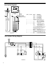
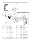
9. Connect the 3/8" white polytubing from the white fitting on the
aeration tank manifold to the air recharge valve on the Iron
Curtain Control Center. Connect the 3/8" black polytubing
from the black fitting on the aeration tank manifold to the air
bleedoff valve on the Iron Curtain Control Center. The 3/8"
white and black tubing are located in the Control Center
box. Cut tubing off to minimal necessary length after
aeration tank and filter tank are in place. Secure tubing
to the plumbing with cable ties provided. Connect drain
discharge line to pressure relief valve.
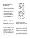
Start-Up
NOTE: The control valve is shipped in the air bleed off
position, see step #3 in flow diagrams, page 20.
1. Close all valves that were previously opened to drain the
plumbing system. Close the inlet and outlet valves on the
Iron Curtain Filter System and open the filter system
bypass valve. If you have a water softener, leave it on
bypass also.
2. Turn on the main water supply valve and flush the water
distribution system. Run water at the nearest cold water
faucet until all the air is relieved, lines are flushed and the
water is clear.
3. Open the inlet valve to the filter no more than 1/4 turn and
allow excess air in the filter tank to escape to drain. After
a steady stream of water is seen at the drain without any
air, proceed to the next step.
4. Close the bypass valve and open the inlet valve all the
way. Leave the outlet valve closed.
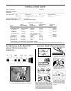
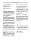
Pre-Installation
Check List
Water Pressure: A minimum of 30 psi at a predetermined
flow rate is required to backwash the filter properly, with a
maximum of 70 psi to be used.*
Actual Influent Flow Rate: (Water available from well
pump, service inlet, etc.) The actual pumping rate must
exceed the backwash rate for the model of filter selected at
a minimum of 30 psi. See actual backwash rates in the
Specifications section on page 7.
Electrical Requirements for Filter Control: A continuous
110 volts is required to cycle the controls and aeration pump.
Make certain the electrical supply is always on and cannot be
turned off with another switch.
Existing Plumbing: The condition of the existing plumbing
should be free from lime and iron build-up. Piping that is
heavily built-up with lime and/or iron should be replaced.
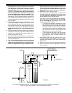
Equipment Location: See Figures 1, 2 & 3 on page 8&9.
Location of Aeration and Filter Tank: See Figures 1, 2 &
3 on page 8&9. These two tanks should be installed after the
pressure tank and as close to each other as practical. If you
want to filter outside hosebibbs, be sure the filter system is
properly sized to handle the flow rates required for extended
periods of time, in addition to the normal household demand.
Drain Lines: All drain lines must be a minimum of 3/4" or
equal to the size of the drain line connection at the control
valve or larger. Avoid overhead drain lines when possible. If
used, overhead drain lines are not to exceed a height of five
feet above the control valve and should be no more than fifty
feet in length.
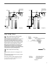
Pressure Relief Valve: A pressure relief valve is installed in
the aeration tank manifold and it is recommended that a
separate drain line be extended toward the floor or to a drain
recepticle. NOTE: Do not plumb to a common drain line with
filter backwash discharge.
Check Valve: On applications where there is a non-filtered
demand for water such as joint wells (where the filter system
is only installed in one of two or more homes), outside
hosebibbs, farms with outbuildings, yard hydrants, etc. a
spring loaded check valve is provided and must be installed
ahead of the aeration tank. See Figures 1, 2 & 3 on page 8&9.
It is recommended to install the check valve in a vertical
upflow position with a minimum 12" water column above the
check valve. This prevents air from escaping past the check
valve. If the check valve is installed in a horizontal position, and
there is a simultaneous demand for both non-filtered and
filtered water, the air head in the aeration tank may escape
backwards past the check valve into the non-filtered water line
and cause air spitting.
By-Pass Valves: Always provide for a three-valve bypass on
the filter system. See Figures 1, 2 & 3 on page 8&9.
Optional Filter Inlet Shut-Off: This valve allows for servicing
of the filter tank and/or filter control valve without draining the
aeration tank. See Figures 1, 2 & 3 on page 8&9.
Filtered Water: Normally, filtered water is furnished to all
household lines; however, outside faucets are typically left
on raw water. If filtered water is provided to outside faucets,
the filter system must be sized accordingly.