


Hickory Industries, Inc.
4900 Westside Avenue, North Bergen, New Jersey 07047
Tel: [201] 223-0050 Fax: [201] 223-0950
N/45 Series Manual12/00
Page 14 of 38
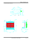
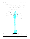
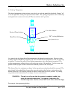
When first installing, after repairing, or after cleaning the units, it is important to make
sure that all components are properly in place.
a. There should be a total of 9, evenly spaced ceramic bricks sitting above each main
pipe burner.
b. The ceramics must be sitting directly on the burners. These ceramic
bricks should also be placed so that they fit between the ceramic support rods.
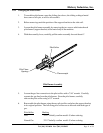
c. The burner pipes should not have any holes (flames) directly below the pilot
burner assembly. If holes (flames) are present, they will overheat the thermocouple or
blow out the pilot flame, preventing the main burner from staying lit.
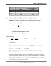
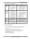
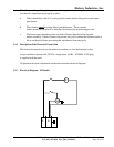
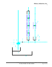
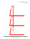
1.15 Electrical Diagram - All Models
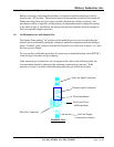
1.14 Description of the Electrical Connection
The electrical connections are to be made in accordance to local and national codes.
All gas machines operate with 120 Volt, single phase, 60 Hz. A NEMA 5-15P plug
is supplied with the units.
All pertinent electrical information can be taken from the electrical diagram.
L N
L
M