


– 10 –
ELECTRICAL CONNECTIONS
WARNING: ELECTRICAL AND GROUNDING CONNECTIONS MUST COMPLY WITH THE APPLICABLE
PORTIONS OF THE NATIONAL ELECTRICAL CODE AND/OR OTHER LOCAL ELECTRICAL CODES.
WARNING: DISCONNECT ELECTRICAL POWER SUPPLY AND PLACE A TAG AT THE DISCONNECT
SWITCH TO INDICATE THAT YOU ARE WORKING ON THE CIRCUIT.
Dishwasher
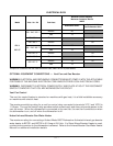
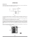
Refer to the wiring diagram attached inside the control box and to the machine data plate for service
size requirements when connecting the dishwasher. Also, refer to Electrical Data, page 12.
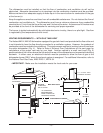
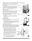
The dishwasher electrical service connection can be made through the 1
1
/8" diameter hole for
3
/4 inch
trade size conduit located at the bottom of the right side of the control box. By removing a knockout,
this hole can be enlarged to 1
3
/4" diameter for 1 inch trade size conduit.
A fused disconnect switch or circuit breaker (not supplied) must be installed in the electrical service
line supplying this dishwasher and should meet the requirements of your local electrical code.
All power supply connections are made at the terminal block 1TB in the control box. The machine must
be grounded according to electrical code(s); a grounding lug is provided in the control box.
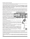
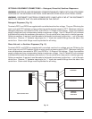
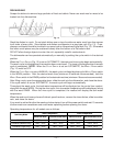
Check Rotation (Three-Phase Machines Only)
Three-phase motors must rotate in the direction of the arrow on the pump housing. In order to check
rotation, observe the motor fan through the end bell. Close the machine doors and press the power
switch to ON. When the machine is completely filled, place the cycle switch (located on the side of the
control box) on MANUAL and place the WASH / RINSE switch (located under the cycle switch) on
WASH. The motor fan must rotate in the direction of the arrow on the pump housing.
If the rotation is incorrect, DISCONNECT ELECTRICAL POWER SUPPLY and interchange any two
of the incoming power supply leads. Reconnect the power supply and verify correct rotation.
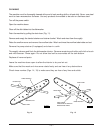
Electric Booster Water Heater
The Electric Booster electrical connection is separate from the dishwasher electrical connection.
Refer to Electrical Data, page 11. Before making electrical connection, test the electrical service to
assure that it agrees with the specifications on the Electric Booster portion of the data plate. Also, refer
to the wiring diagram attached inside the cover of the control box.
A fused disconnect switch or circuit breaker must be installed in the electrical service line supplying
this booster and should meet the requirements of your local electrical code.
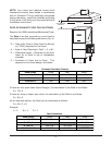
The electric booster service connection is made through the 1
3
/4" hole for 1 inch trade size conduit
located at the bottom of the control box. If the booster is three phase, the electrical connection is made
to the contactor 3CON in the control box. If the booster is single phase, the electrical connection is
made to the terminal block 4TB in the control box. The machine must be grounded according to
electrical code(s); a grounding lug is provided in the control box.