


– 7 –
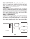
With Electric Booster Water Heater
The water supply line is connected to the flow control ahead of the line strainer below the booster with
3
/4" pipe. A manual shut off valve and pipe union are required.
The water supply should have a minimum temperature of 110°F, and a flowing pressure of 15 – 25 psig
at the pressure gauge on top of the machine. If the flowing pressure exceeds 25 psig, a pressure
reducing valve (not supplied) must be installed in the water supply line. CAUTION: The water
pressure regulator must have a relief by-pass. Failure to use the proper type of pressure
regulator may result in damage to the unit.
Incoming water temperature below 110°F may require the wash cycle time to be extended from 40 to
60 seconds. To have the cycle time adjusted, contact your local authorized Hobart Service Office.
When the fill / final rinse valve is on, water from the booster tank enters the dishwasher through the
final rinse arms. During the rinse cycle, this water is 180° F. Water will likely dribble out of the lower
rinse arm into the tank between cycles due to the natural expansion of water as it is being heated.
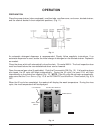
GAS TANK HEAT (When Specified)
Check the gas data plate attached to the
dishwasher or the tag attached to the incoming
gas piping for the type of gas to be used.
Connect the gas supply to the
1
/2" NPT gas
inlet at the manual gas valve. The burner is
not adjustable. The maximum flowing inlet
gas pressure must not exceed the Maximum
value in the table. If line pressure exceeds
the Maximum value in the table, an additional
regulator valve (not supplied) must be installed
in the supply line.
Static inlet line pressure should not exceed 14" W.C. The minimum value is
for purpose of input adjustment.
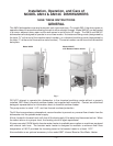
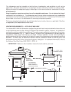
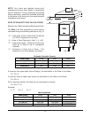
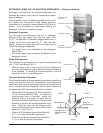
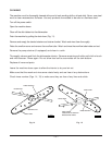
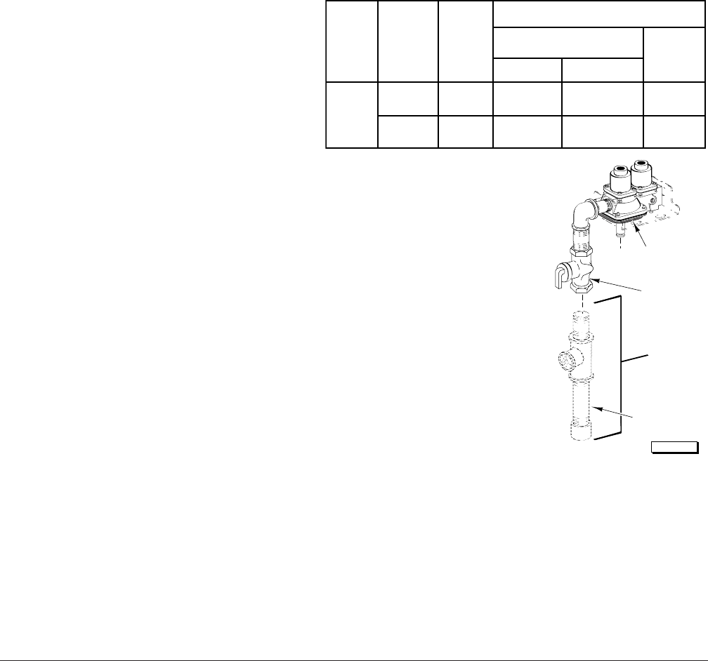
The gas valve (Fig. 3) is provided with a pressure tap to measure the gas
pressure downstream, which is also the manifold pressure. Gas supply piping
must have a sediment trap (supplied by others) installed ahead of the
dishwasher's gas control (Fig. 3).
NOTE: DO NOT use Teflon tape on gas line pipe threads. For gas line pipe
connections, use L
OCTITE 565, Hobart part 546292, or a flexible sealant
suitable for use with Natural and Propane Gases.
The appliance and its gas connections must be leak tested before placing the
appliance in operation. Use soapy water for leak test. DO NOT use open
flame. The installation must conform with local codes, or in the absence of
local codes, with the National Fuel Gas Code, ANSI Z223.1 (latest edition).
Copies may be obtained from American Gas Association, Inc., 1515 Wilson
Boulevard, Arlington, VA 22209.
The appliance and its individual shutoff valve must be disconnected from the gas supply piping system
during any pressure testing of that system at test pressures in excess of
1
/2 psig (3.45kPa).
The appliance must be isolated from the gas supply piping system by closing its individual manual
shutoff valve during any pressure testing of the gas supply piping system at test pressures equal to or
less than
1
/2 psig (3.45kPa).
Dissipate test pressure from the gas supply line before re-connecting the appliance and its manual
shutoff valve to the gas supply line. Caution: Failure to follow this procedure may damage the gas
valve.
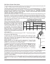
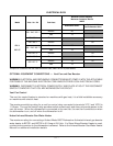
GAS PRESSURE SPECIFICATION
[ FLOWING GAS PRESSURE — NOT STATIC ]
Model
Type
of
Gas
BTU/HR
Inches W.C. (Water Column)
Incoming Line Pressure
Manifold
Pressure
Minimum Maximum
AM14
AM14C
Natural 20,000 4.5 10.5 3.2
Propane 20,000 9.0 13.0 9.0
Fig. 3
PL-53347
By Others
Sediment Trap
Gas Valve
Manual Valve