– 5 –
STANDARD EQUIPMENT
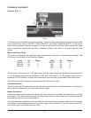
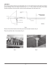
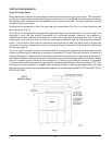
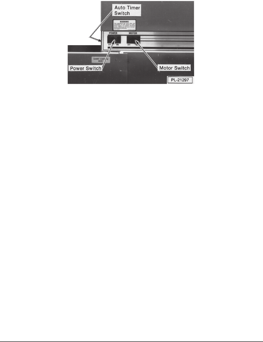
Controls (Fig. 1)
Fig. 1
The controls are mounted on top of the chamber. There are three operational control switches housed
in the control box: Power (ON-OFF); Motor (ON-OFF); and Timer (MANUAL-AUTO). A pilot circuit
transformer provides a reduced voltage of 115 volts for the machine controls. When equipped for gas
heat, a step-down transformer provides a reduced voltage of 24 volts for the igniter board(s) and
valves.
Motor and Pump Units
The wash/rinse pump(s) are centrifugal-type cast stainless steel with a stainless steel impeller. The
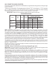
2 HP motor is available in the following voltages:
Volts Hz Phase Volts Hz Phase
208-240 60 1 380-415 50 3
208-240 60 3 380 60 3
200-240 50 3 480 60 3
600 60 3
The conveyor drive motor is a
1
/6 HP gear motor with the same voltage as the wash/rinse pump motor.
A 1 HP prewash pump motor is standard on CRS and CCS models. A 2 HP prewash pump motor is
standard on CPW models. Voltage and construction are the same as the wash/rinse pump motor.
All motors have built-in thermal overload protection with manual reset.
Vacuum Breakers
The final rinse and fill lines contain an atmospheric vacuum breaker that prevents any reverse flow of
water from the dishwasher into the potable water supply.
Heater Protection
A float-activated switch located in the wash tank (and rinse tank if included) automatically turns off the
heat supply, if the water level is too low. Once the water returns to the proper level, the heating circuit
becomes operational if heat is demanded.
An overtemperature protector is also provided for electric and gas tank heat, and for built-in booster
if provided. If overheating should occur, the heat supply will be turned off. Turn the Power switch OFF
and contact your local Hobart service office.


