


– 5 –
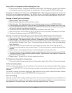
ASSEMBLING THE STAND TO THE OVEN
Attach each of the four leg assemblies to the bottom of the
oven with the 24 bolts and lockwashers (six per leg).
Carefully raise the oven to the normal position.
Attach the undershelf to the legs with eight bolts and
lockwashers (two per leg).
Install the rack guides into the shelf at the desired locations
(for pan or flat rack), then attach the rack supports to the
top end of the rack guides. Attach rack supports to the leg
assembly by removing one middle bolt and reattaching the
back through the end holes in the rack support (Fig. 2).
Fig. 2
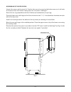
ELECTRICAL CONNECTIONS
WARNING: ELECTRICAL AND GROUNDING CONNECTIONS MUST COMPLY WITH THE
APPLICABLE PORTIONS OF THE NATIONAL ELECTRICAL CODE ANSI/NFPA70 (LATEST EDITION)
AND/OR OTHER LOCAL ELECTRICAL CODES.
WARNING: DISCONNECT ELECTRICAL POWER SUPPLY AND PLACE A TAG AT THE DISCONNECT
SWITCH TO INDICATE THAT YOU ARE WORKING ON THE CIRCUIT.
Remove the wiring compartment cover on the front of the oven. Remove the appropriate knockout on
the bottom of the oven and attach the power supply conduit to the bottom of the oven.
Comply with the wiring diagram (located inside the right side panel) when making connections to the
electrical supply lines.
Replace the wiring compartment cover and right side panel. Turn on the power supply.
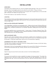
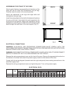
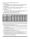
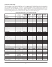
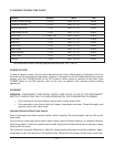
ELECTRICAL DATA
208-240 V 480 V
NOMINAL AMPERES PER LINE WIRE
TOTAL
3-PHASE LOADING 3-PHASE LOADING
3-PHASE 1-PHASE
KW KW PER PHASE KW PER PHASE 208 V 240 V 480 V
208 V 240 V 480 V
L1-L2 L2-L3 L1-L3 L1-L2 L2-L3 L1-L3
L1 L2 L3 L1 L2 L3 L1 L2 L3
Single Oven 12.5 4 4 4.5 4 4 4.5 35 33 35 33 29 33 14.4 15.3 15.3 60 52 26
Stacked Oven 25 8 8 9 8 8 9 70 66 70 66 58 66 28.8 30.6 30.6 120 104 52
BACK
FRONT
PL-53274