


OV500 SERIES RACK OVEN - ELECTRICAL OPERATION
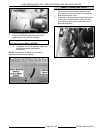
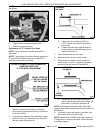
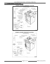
3. The shutters are the short L shaped panels of stainless steel located on the right rear corner panel of the
bake chamber. There are 12 shutters per oven, consisting of 24 adjustable air volume settings and 12
adjustable angle settings.
4. Air volume adjustments modifies the heat from top to bottom of rack(s).
5. Shutter angle adjustments direct the heat to side or center of individual pans on a rack.
6. Oven pressure panel feeler gauge Part No. 01-1M5689-1. Do not discard feeler gauges.
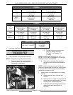
Evaluating Product
1. Observe a rack of product.
A. Evaluate the rack of product.
1) If the product is the same color from edge to center of trays, but the color varies from top to bottom
of the rack, then an air volume adjustment is needed.
2) If individual trays of the product are not the same color from edge to center, then the angles need to
be adjusted.
2. Adjust as necessary.
3. If satisfactory results can not be achieved after two or three attempts at adjusting, call Bakery Product
Support.
NOTE: Changes in product whether raw, mixed, different mixes, or old mix can affect the bake.
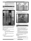
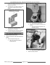
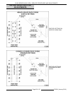
Air Volume Adjustment
1. Allow oven to cool.
2. Determine the shutter that needs adjusted.
NOTE: Always start at the dark areas and decrease opening of shutter to prevent air volume depletion.
3. Decrease shutter opening in area where the product is dark and adjust the shutter only 1/32 of an inch at a
time.
4. In rare cases it will be applicable to increase shutter openings where the product is light. ONLY if
recommended by Bakery Product Support.
5. Validate adjustments by performing a test bake with the same type of product.
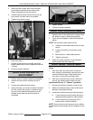
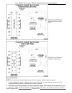
Shutter Angle Adjustment
Make corrections with air volume adjustments before making any shutter angle adjustments. Changes to the
factory shutter angle settings should only be made to correct specific baking issues that air volume adjustments
cannot correct, contact Bakery Product Support for assistance.
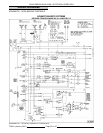
ELECTRICAL OPERATION
COMPONENT FUNCTION
Controller ................ Controls oven operation.
Transformers ............. Supplies 24VAC to ignition module, controller door switch, and CR4.
Door Switch .............. Allows control to monitor door position and directs power to rack rotation motor
and rack lift motor.
Draft Inducer
Pressure Switch ........... Senses vacuum created by draft inducer fan. Prevents burner ignition if sufficient
combustion air is not present.
Hood Pressure Switch ...... Senses vacuum in hood vent. Prevents burner ignition if sufficient exhaust
vacuum is not present.
Hi Limit Thermostat ........ Prevents oven temperature from exceeding 608EF. (320EC.) (manual reset).
Gas Valve ................ When energized, allows gas to flow to burners.
F25361 (January 2010)
Page 47 of 60