


– 3 –
INSTALLATION
Immediately after unpacking the dishwasher, check for possible shipping damage. If the machine is
found to be damaged, save the packaging material and contact the carrier within 15 days of delivery.
Prior to installation, test the electrical service to make sure it agrees with the specifications on the
machine data plate.
LOCATION AND LEVELING
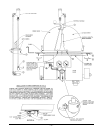
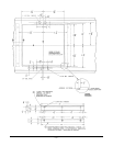
The dishwasher must be installed per the drawings on pages 4 – 6. Stainless steel is the recommended
material for the table. The table should be a convenient height for the operator. The dishwasher should
be level, both front-to-back and side-to-side. The table should drain into the dishwasher. Seal around
the table flange with an NSF approved sealer.
PLUMBING CONNECTIONS
WARNING: PLUMBING CONNECTIONS MUST COMPLY WITH APPLICABLE SANITARY, SAFETY,
AND PLUMBING CODES.
The plumber who connects this machine is responsible for making certain that incoming water lines are
THOROUGHLY FLUSHED OUT before connecting to any manual valve or solenoid valve.
This "flush-out" is necessary to remove all foreign matter, such as chips (resulting from cutting or
threading of pipes), pipe joint compound from the lines, or, if soldered fittings are used, bits of solder
or cuttings from tubing. Debris, if not removed, may lodge in the valves and render them inoperative.
Manual valves or solenoid valves fouled by foreign matter, and any expenses resulting from this
fouling, are NOT the responsibility of the manufacturer.
Hot Water Connection
Water must be proper hardness. Recommended hardness range is 4 – 6 grains / gallon. Lower
hardness can promote corrosion, higher hardness may cause excessive formation of lime scale. A line
strainer should be installed in the water supply line at the time of installation. The line strainer prevents
frequent clogging of the rinse nozzles and requires only occasional cleaning.
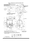
The water supply connection point has a
1
/2" NPT internal thread (see FILL CONNECTION, Fig. 1). The
water supplied to this machine must be 180°F and have a flow pressure of 20 – 25 psig for most effective
rinsing. CAUTION: The water pressure regulator must have a relief by-pass. Failure to use the
proper type of pressure regulator may result in damage to the unit. After installation, a pressure
gauge must be visible and access must be available to service connections and areas which require
cleaning.
Drain Connection
Connect the drain to the sewer from the 1
1
/4" NPT tapped connection, provided. Use a 1
1
/4" – 1
1
/2"
coupling to provide 1
1
/2" line to sewer. If a grease trap is required by code, it should have a minimum
flow capacity of approximately 28 gallons per minute.
ELECTRICAL CONNECTIONS
WARNING: ELECTRICAL AND GROUNDING CONNECTIONS MUST COMPLY WITH APPLICABLE
PORTIONS OF THE NATIONAL ELECTRICAL CODE AND/OR OTHER LOCAL ELECTRICAL CODES.
WARNING: DISCONNECT THE ELECTRICAL POWER SUPPLIES AND PLACE A TAG AT THE
DISCONNECT SWITCHES INDICATING THAT YOU ARE WORKING ON THE CIRCUITS.
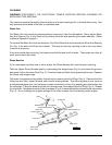
Make the main electrical connection at the motor junction box (Fig. 1) where a knockout for
1
/2" conduit
is provided. Make the electrical connection for the electric heater circuit at the electric box for the
electric heater where a knockout for
1
/2" conduit is provided. Refer to the wiring diagram attached to
the inside of the control box cover. All electrical supply lines to the machine must be disconnected
when disconnection is required.