EXCEL 10 W7753A UNIT VENTILATOR CONTROLLER
3 95-7520—02
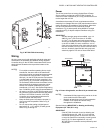
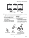
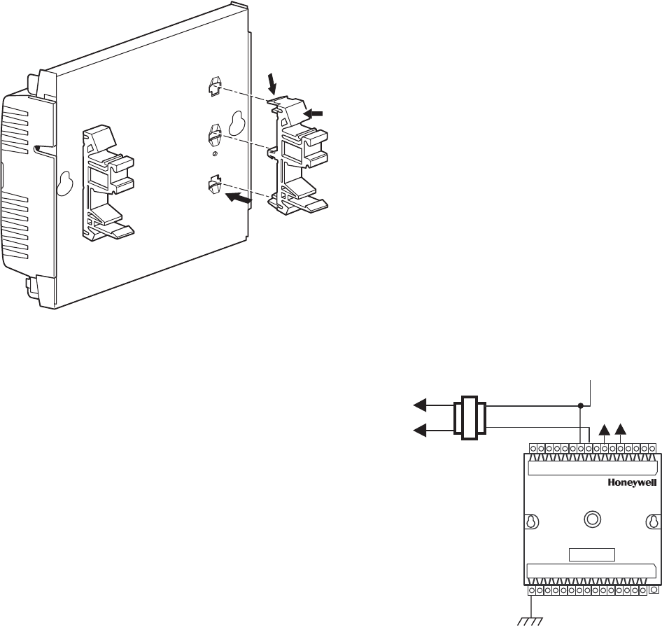
Fig. 3. W7753A DIN rail mounting.
Wiring
All wiring must comply with applicable electrical codes and
ordinances or as specified on installation wiring diagrams.
Controller wiring on the W7753A is terminated to the screw
terminal blocks located on the top and the bottom of the
controller.
NOTES:
— For multiple controllers operating from a single
transformer, the same side of the transformer
secondary must be connected to the same power
input terminal in each controller. The ground
terminal (1 on the W7753A) must be connected to
a verified earth ground for each controller in the
group (see Fig. 5). (Controller configurations are
not necessarily limited to three controllers, but the
total power draw including accessories cannot
exceed 100 VA when powered by the same
transformer (U.S. only). See System Engineering
form 74-2964 for power wiring recommendations.)
— All loads on an Excel 10 W7753A Controller must
be powered by the same transformer that powers
the Excel 10 W7753A Controller. A W7753A
Controller can use separate transformers for
controller power and load power.
— Keep the earth ground connection (terminal 1)
wire run as short as possible. Refer to Fig. 9
through 14.
—Do not connect the analog or digital ground
terminals (5, 8, 11, 27 and 30) to earth ground.
Refer to Fig. 9 through 14.
Power
The 24 Vac power from an energy-limited Class II Power
Source must be provided to each W7753A Controller. To
conform to Class II restrictions (U.S. only), transformers must
not be larger than 100 VA.
A transformer that meets CE mark requirements and that
meets the Low Voltage Directive (LVD) requirements must be
used in Europe for all installations of this product. More than
one W7753A Controller can be powered by a single
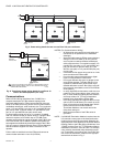
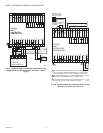
transformer. Fig. 4 shows power wiring details for a single
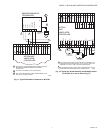
controller and Fig. 5 depicts multiple controllers using one
transformer.
IMPORTANT
Use the heaviest gauge wire available, up to 14
AWG (2.0 mm
2
) with a minimum of 18 AWG
(1.0 mm
2
), for all power and earth ground wiring.
Screw type terminal blocks are designed to accept
up to two 14 AWG (2.0 mm
2
) conductors, one on
each side of the terminal screw. More than two wires
that are 14 AWG (2.0 mm
2
) can be connected with a
wire nut. Include a pigtail with this wire group and
attach the pigtail to one side of the terminal block.
Fig. 4. Power wiring details; one Excel 10 per transformer.
NOTES:
— Unswitched 24 Vac power wiring can be run in the
same conduit as the E-Bus cable.
— Maintain at least three-inch (76 mm) separation
between Triac outputs and E-Bus wiring
throughout the installation.
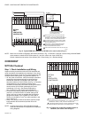
See the following IMPORTANT on Heating and Cooling
Equipment (UL 1995, U.S. only).
IMPORTANT
If the W7753A Controller is used on Heating and
Cooling Equipment (UL 1995, U.S. only) and the
transformer primary power is more than 150 volts,
connect the transformer secondary to earth ground
(see Fig. 6). For these applications, only one
W7753A Excel 10 controller can be powered by each
transformer.
M6857
1
2
3
M12681
CONNECT POWER TO
TERMINALS 24 AND 25
TRIAC LINES
TO ACTUATORS
AND
CONTACTORS
TRANSFORMER
W7753A
EARTH
GROUND
2022
24
25
1
OUTPUT
DEVICE
POWER


