EXCEL 10 W7753A UNIT VENTILATOR CONTROLLER
9 95-7520—02
Verify Termination Module Placement
The installation wiring diagrams should indicate the locations
for placement of 209541B Termination Module(s). Refer to the
E-Bus Wiring Guidelines, form 74-2865, and the Excel 10 FTT
Termination Module Installation Instructions, form 95-7554.
Correct placement of the termination module(s) is required for
proper E-Bus communications.
Step 2. Startup
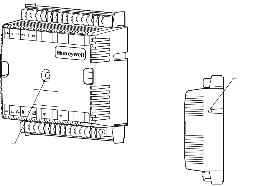
W7753A CONTROLLER STATUS LED
The LED on the front and center of a W7753A Controller
provides a visual indication of the status of the controller. See
Fig. 15. When the W7753A receives power, the LED should
appear in one of the following allowable states:
1. Off—no power to the processor.
2. Continuous On—processor is in initialized state.
3. Slow Blink—controlling, normal state.
4. Fast Blink—when the Excel 10 has an alarm condition.
Fig. 15. LED location on W7753A.
ALARMS
When an Excel 10 has an alarm condition, it reports it to the
central node on the E-Bus (typically, the Excel 10 Zone
Manager, or Small Building Controller). See Table 1. The
information contained in an alarm message follows:
• Subnet Number: This is the E-Bus subnet that contains the
Excel 10 node that has the alarm condition. Subnet 1 is on
the Zone Manager side of the router; Subnet 2 is on the
other side of the router.
• Node Number: This is the Excel 10 node that has the alarm
condition (see Network Statics).
Alarm Type: The specific alarm being issued. An Excel 10 can
provide the alarm types listed in Table 1.
Broadcasting the Service Message
The Service Message allows a device on the E-Bus to be
positively identified. The Service Message contains the
controller ID number and, therefore, can be used to confirm
the physical location of a particular Excel 10 in a building.
There is one method of broadcasting the Service Message
from an Excel 10 W7753A Controller. This uses a hardware
push button on the side of the controller (see Fig. 16).
When an Assign ID command is issued from the
commissioning tool, the node goes into the
SERVICE_MESSAGE mode for five minutes. In the
SERVICE_MESSAGE mode, pressing the service pin on the
controller or the bypass button on a wall module causes the
Service Message to be broadcast on the network. All other
functions are normal in the SERVICE_MESSAGE mode.
Step 3. I/O Tests
The controller must be configured using the Excel 10 E-Vision
PC configuration tool. Once this is done, the W7753A can be
commanded to MANUAL mode, and each output can be
exercised/viewed to verify proper wiring connections and
equipment operation. See the Excel 10 E-Vision Users Guide,
form 74-2588 for details on configuring and testing W7753A
Controllers.
Fig. 16. Location of the service pin button.
Step 4. Verify Sequences of Operation
For the detailed descriptions of the sequences of operation,
see the Excel 10 Unit Ventilator System Engineering,
form 74-2964 Appendix B.
M12697
1
23
45678
910
11 12
13 14
15
J3
31 30
29 28 27
26 25
24
23 22
21
20
19 18 17
16
E
GND
LED
BYPASS
SNSR
GND
SET PT
AI-1
OHM
GND
A1-2
OHM
AI-3
V/mA
GND
AI-4
V/mA
22VDC
OUT
E-BUS
E-BUS
JACK
DI-4 GND
DI-3
DI-2
GNDDI-1
24
VAC
24
VAC
COM
1
OUT
2
OUT
3
OUT
4
OUT
5
OUT
6
OUT
7
OUT
8
OUT
W7753A
STATUS
LED
M10094
SERVICE
PIN
BUTTON


