


EXCEL 10 W7753A UNIT VENTILATOR CONTROLLER
95-7520—02 8
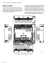
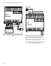
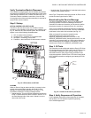
Fig. 13. Typical PWM Valve Actuator to W7753A. (For note 2, refer to Fig. 8.)
NOTE: Make sure to set the Configuration DIP Switch as shown in Fig. 13. Switches 1 through 3 set the timing of the ML7984B
valve actuator to match the W7753A outputs (0.1 sec. Min. with a max. time of 25.6 sec.).
Switch 4 determines the action of the actuator (Off = Direct Acting, On = Reverse Acting).
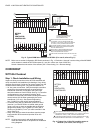
CHECKOUT
W7753A Checkout
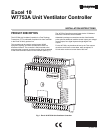
Step 1. Check Installation and Wiring
Inspect all wiring connections at the W7753A terminals and
verify compliance with installation job drawings. If any wiring
changes are required, first be sure to remove power from the
controller before starting work. Pay particular attention to:
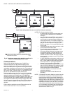
— 24 Vac power connections. Verify that multiple controllers
powered by the same transformer are wired with the
transformer secondary connected to the same input
terminal numbers on each W7753A. See Fig. 5. (Controller
configurations are not necessarily limited to three
controllers, but the total power draw including accessories
cannot exceed 100 VA when powered by the same
transformer (U.S. only). See System Engineering,
form 74-2964, for power wiring recommendations.
— Controller wiring. Be sure that each controller is wired
(terminal 1) on the W7753A to a verified earth ground
using a wire run as short as possible with the heaviest
gauge wire available, up to 14 AWG (2.0 mm
2
) with a
minimum of 18 AWG (1.0 mm
2
) for each controller in the
group. See Fig. 4.
— Verify Triac wiring to external controllers uses the proper
load power/24 Vac hot terminal (terminal 25 on the
W7753A).
NOTE: All wiring must comply with applicable electrical
codes and ordinances or as specified on installation
wiring diagrams.
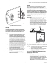
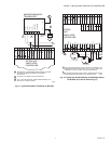
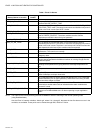
Fig. 14. Typical 2 to 10 Volt DC humidity sensor to
W7753A. (For note 2, refer to Fig. 8.)
12345678
E-BUS
24 VAC
1
2
E-BUS
E GND
GND
SNSR
SETPT
LED
BYPASS
GND
GND
9101112 14 J315
31 30 29 28 27 26 25 24 23 22 21 20
24 VAC COM
E-BUS
JACK
22 VDC OUT
19 18 17 16
AI-1 OHM
AI-2 OHM
AI-4 V/mA
OUT 7
OUT 6
OUT 5
OUT 4
OUT 8
OUT 1
OUT 3
OUT 2
AI-3 V/mA
13
DI-2
DI-4
DI-1
DI-3
M12694
GND
GND
TRIAC EQUIVALENT CIRCUIT
24 VAC
+
-
2
1
2
3
3
4
EARTH GROUND WIRE LENGTH SHOULD BE HELD
TO A MINIMUM. USE THE HEAVIEST GAUGE WIRE
AVAILABLE, UP TO 14 AWG (2.O MM
2
) WITH A MINIMUM
OF 18 AWG (1.O MM
2
), FOR EARTH GROUND WIRE.
TO ASSURE PROPER ELECTRICAL CONTACT, WIRES
MUST BE TWISTED TOGETHER BEFORE INSERTION
INTO THE TERMINAL BLOCK.
MAKE SURE ALL TRANSFORMER/POWER WIRING
IS AS SHOWN:REVERSING TERMINATIONS WILL
RESULT IN EQUIPMENT MALFUNCTION.
TURN POWER OFF BEFORE SETTING THE DIP SWITCHES.
1234
4
24 (H)
24 (N)
PWM
(H 24 VAC)
PWM OUTPUT
FROM CNTRL
PWM VALVE ACTUATOR
PWM VALVE
ACTUATOR
ML7984B
T6 T5 C B W R
ON
OFF
CONFIGURATION DIP SWITCHES
(LOCATED ADJACENT TO THE
INPUT TERMINAL BLOCK)
W7753A
UNIT
VENTILATOR
CONTROLLER
12345678
E-BUS
24 VAC
W7753A
UNIT
VENTILATOR
CONTROLLER
1
2
E-BUS
E GND
GND
GND
OUT
+V
SNSR
SETPT
LED
BYPASS
GND
GND
9101112 14 J315
31 30 29 28 27 26 25 24 23 22 21 20
24 VAC COM
E-BUS
JACK
22 VDC OUT
19 18 17 16
AI-1 OHM
AI-2 OHM
AI-4 V/mA
OUT 7
OUT 6
OUT 5
OUT 4
OUT 8
OUT 1
OUT 3
OUT 2
AI-3 V/mA
13
DI-2
DI-4
DI-1
DI-3
M12696
GND
GND
TRIAC EQUIVALENT CIRCUIT
C7600B
1
2
EARTH GROUND WIRE LENGTH SHOULD BE HELD TO A MINIMUM. USE
THE HEAVIEST GAUGE WIRE AVAILABLE, UP TO 14 AWG (2.O MM
2
) WITH
A MINIMUM OF 18 AWG (1.O MM
2
), FOR EARTH GROUND WIRE.
TO ASSURE PROPER ELECTRICAL CONTACT, WIRESMUST BE TWISTED
TOGETHER BEFORE INSERTIONINTO THE TERMINAL BLOCK.
HUMIDITY
SENSOR
(2 TO 10 VOLT)