SERVICE INSTRUCTIONS
Bin Control Thermostat Replacement Procedure
To ensure proper operation, follow the instructions below:
[AM-100BAE]
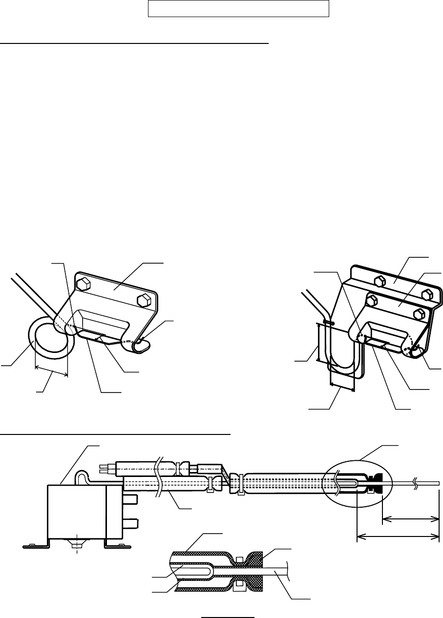
1) Make a 40 mm (1.6”) diameter loop.
2) Locate the loop below the Thermostat
Capillary (Bulb).
3) Manually bend the Capillary to keep it
15 mm (0.6”) forward from the through
hole position on the Holder.
4) Turn up the end of the Capillary.
[AM-150BAF/BWF]
1) Make a 40 mm (1.6”) ID U-bend.
2) Locate the U-bend 60 mm (2.4”) below
the Thermostat Capillary (Bulb).
3) Manually bend the Capillary to keep it
15 mm (0.6”) forward from the through
hole position on the Holder.
4) Turn up the end of the Capillary.
Bin Control Thermostat Assembly Details
[NOTE]
1) Run Cord Heater along with Capillary of Thermostat and bind them tightly with
Aluminum Tape (Form end to end of Cord Heater).
2) Do not overheat Flexible Tube during shrinking process.
17
40 mm (1.6”) DIA
Capillary (Bulb)
End
Holder
Capillary (Bulb)
15 mm (0.6”)
Loop
Through Hole
DETAIL A
150mm
(5.9”)
210mm
(
8.3”
)
A
Capillary (Bulb)
Thermostat
Silicone Tube
Cord Heater
Flexible Tube
Silicone Tube
Seal
Capillary (Bulb)
End
Holder
Capillary (Bulb)
15 mm (0.6”)
60 mm (2.4”)
Through Hole
Bracket - Holder
40 mm (1.6”)


