


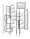
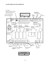
C. Sequence of Operation
The steps in the sequence are as outlined below. When power is supplied, the power
switch is in the "ON" position, the door switch is engaged, and the control switch is in the
"ICE" position, the "POWER" LED on the control board comes on.
1. Fill Cycle
WV opens and the reservoir lls with water until UF/S closes. Note: GM will not start
unless UF/S is closed. For details, see "IV. Service Diagnosis".
2. Ice Purge Cycle (60 seconds)
"GM" LED is on. WCR energizes, closing the low water safety circuit and de-energizing
the WV. GM, GMPR, HCR, and HTR energize. GM runs for 60 seconds to clear any ice
from the evaporator.
3. Freeze Cycle
"COMP", "GM" LEDs are on. Comp and FMS energize. As the water in the evaporator
cools, ice starts forming within 4 to 6 minutes. This time frame depends on the inlet water
and ambient temperature conditions. UF/S and LF/S operate WCR and WV as needed
to continue the icemaking process. This continues until BC shuts the icemaker down or
power is turned off to the icemaker.
4. Drain Cycle
hour DT activates, "FLUSH" LED is on after 50 second shutdown sequence. Comp
and FMS de-energize 90 seconds after the hour DT activates, GM, GMPR, HCR,
and HTR de-energize 60 seconds later. DV then energizes and remains energized for
0 minutes.
5. Shutdown
BC is activated and a 50 second shutdown sequence begins. After BC has been
open for 90 seconds, Comp and FMS de-energize, AM energizes for 0.6 seconds, and
60 seconds later GM, GMPR, HCR, and HTR de-energize.
Legend: AM–agitating motors; BC–bin control; Comp–compressor; DT–drain timer;
FMS–self-contained fan motor; GM–gear motor; GMPR–gear motor
protect relay; HCR–heater control relay; HTR–extruding head heater;
LF/S–lower oat switch; UF/S–upper oat switch; WCR–water control relay;
WV–inlet water valve