


36
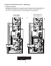
IV. Service Diagnosis
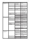
A. Diagnostic Procedure
This diagnostic procedure is a sequence check that allows you to diagnose the electrical
system and components. Before proceeding, check for correct installation, adequate
water supply (minimum of 0 PSIG, maximum of 3 PSIG) and proper voltage per unit
nameplate. Always choose a white neutral wire to establish a good neutral connection
when checking voltages. LEDs on the control board correspond to the components as
they energize.
) Move the control switch to the "OFF" position, then turn off the power supply. Remove
the upper and lower front panels. Conrm the power switch is in the "ON" position and
the door switch is engaged.
) Turn on the power supply, then move the control switch to the "ICE" position. The
"POWER" LED is on. The "POWER" LED will not come on if the door switch is not
engaged.
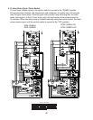
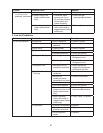
3) Fill Cycle – The inlet water valve energizes. The reservoir lls. The lower oat switch
closes. Nothing occurs at this time. The reservoir continues to ll until the upper oat
switch closes, energizing the water control relay, which closes the low water safety
circuit and de-energizes the inlet water valve. Diagnosis: Check that the inlet water
valve lls the reservoir. If not, check for water supply line shut-off valve closed, clogged
water lters, clogged inlet water valve screen, power circuit to the inlet water valve
(power switch, door switch, power protect relay contacts, transformer, fuses, high
pressure switch, bin control, control switch, oat switch, water control relay contacts),
and the coil on the inlet water valve. Check that the inlet water valve shuts off when
the upper oat switch closes. If not, check the oat switch, water control relay, and inlet
water valve.
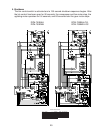
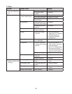
4) Ice Purge Cycle – "GM" LED is on (60 second short cycle protection). The 60 second
timer starts, the water control relay remains energized, the gear motor, gear motor
protect relay, heater control relay, and heater energize. Diagnosis: Check that the
gear motor starts. If not, check that the water control relay is energized (inlet water
valve should be closed). Check the low water safety circuit on the water control relay
(terminals 4 and 6), check for 5/0V at the K connector "COM" terminal to neutral
and "NO" terminal to neutral on the control board (see wiring diagram), check the gear
motor fuse (overload protector), thermal protector, gear motor capacitor, and motor
windings. If the gear motor starts, but the auger does not turn, check the gear motor
coupling between the auger and the gear motor. If the compressor starts at the same
time the gear motor starts, check the X compressor relay on the control board.
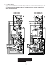
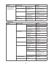
5) Freeze Cycle – "COMP", "GM" LEDs are on. The compressor and fan motor energize,
the water control relay, gear motor, gear motor protect relay, heater control relay, and
heater remain energized. Ice production begins 4 to 6 minutes after the compressor
and fan motor start depending on ambient and water temperature conditions. The
upper oat switch and lower oat switch operate the water control relay and inlet
water valve as needed to continue the icemaking process. Diagnosis: Check that
the compressor and fan motor are running. If not, check for voltage on and to the
compressor (X relay on the control board). Check that the gear motor protect relay
circuit terminals 3 and 5 are closed, check the compressor internal overload (thermal
protector), the compressor capacitors, fan capacitor, and voltage to the fan motor.