


9
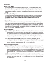
f) High Voltage and Low Voltage Cut-outs
The maximum and minimum allowable supply voltages of this icemaker are limited by
the high voltage (147Vac±5% or more) and low voltage (9Vac±5% or less) cut-outs.
When high voltage (147Vac±5% or more) is present, the icemaker automatically stops
and the control board signals with a 7-beep alarm every 3 seconds.
When low voltage (9Vac±5% or less) is present, the icemaker automatically stops and
the control board signals with a 6-beep alarm every 3 seconds.
When the proper supply voltage is resumed, the icemaker automatically starts running
again.
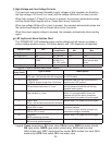
g) LED Lights and Alarm Safeties Chart
The "POWER OK" LED indicates proper control voltage and will remain on unless a
control voltage problem occurs. For further details, see "II.B. Sequence of Operation."
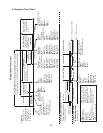
Sequence Step LED
Energized
Components Min. Max.
Fill Cycle WTRIN WV - -
Ice Purge Cycle GM GM, FM/FMR 5 min. 5 min.
Freeze Cycle (with rell) GM, WTRIN* (rell),
COMP
GM, Comp,
FM/FMR, LLV,
SLV, WV* (rell)
- *On until UF/S closes.
Alarm sounds after
90 sec.
Drain Cycle FLUSH (Drain) DV sec. 10 min.
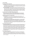
The built-in alarm safeties shut down the unit.
No. of Beeps
(every 5 sec.)
Type of Alarm Reset Options
1 Low Water Safety
UF/S open > 90 seconds after WV energized.
Automatic reset once water supply is restored
and UF/S closes.
Control Switch
In "DRAIN" position longer than 15 minutes.
Automatic reset once the control switch is
moved to the "ICE" position.
3 High Pressure Switch
First and second activation in 1 hour.
Automatic reset once pressure drops below
the high pressure threshold and the high
pressure switch closes.
4 High Pressure Switch
Third activation in 1 hour.
Call for service. To avoid possible catastrophic
failure, it is recommended to leave the
icemaker off until this alarm is resolved.
Manual reset. Turn power off and on again.
5 Freeze Timer
WV off > 30 minutes since last WV activation.
Manual reset. Turn power off and on again.
6 Low Voltage
(9Vac ±5% or less)
"POWER OK" LED turns off if voltage
protection operates.
The control voltage safeties automatically
reset when voltage is corrected.
7 High Voltage
(147Vac ±5% or more)
8 Gear Motor
GMPR contacts fail to close.
Manual reset. Turn power off and on again.
9 Infrared Sensor (S1 dip switch 7)
MBC actuator paddle engaged.
Manual reset. Turn power off and on again.
Legend: Comp–compressor; DV–drain valve; FM–fan motor; FMR–fan motor-remote;
GM–gear motor; GMPR–gear motor protect relay; LLV-liquid line valve
(MLH model only); MBC–mechanical bin control; SLV–suction line valve (MLH
model only); UF/S–oat switch; WV–inlet water valve