


90
18) Open the condenser water supply line shut-off valve. If connected to a closed loop
water supply, also open the condenser return outlet shut-off valve.
19) Check for water leaks.
0) Replace the panels in their correct positions.
1) Turn on the power supply.
H. Adjustment of Water Regulating Valve - Water-Cooled Model
The water regulating valve (also called "water regulator") is factory-adjusted. No adjustment
is required under normal use. Adjust the water regulator, if necessary, using the following
procedure.
1) Prepare a thermometer to check the condenser outlet temperature. Attach a pressure
gauge to the high-side line of the system.
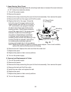
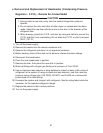
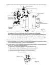
) Five minutes after a freeze cycle starts,
conrm that the thermometer reads 104°F
to 115°F (40°C to 46°C). If it does not,
rotate the adjustment screw by using a at
blade screwdriver until the temperature
is in the proper range. See Fig. 13. Next,
check that the reference pressure is in the
range indicated in the Head Pressure table
in the Performance Data section. If it is not
in the proper range, verify the refrigerant
charge.
3) Check that the condenser drain temperature is stable.
I. Removal and Replacement of Fan Motor (air-cooled and remote
air-cooled models)
Note: When replacing a fan motor with defective winding, it is recommended that a new
capacitor be installed.
1) Turn off the power supply.
) Remove the panels.
3) Remove the junction box cover from the remote condenser unit (remote air-cooled
model).
4) Disconnect the fan motor wires and the capacitor wires.
5) Remove the fan motor bracket (air-cooled model), fan motor, and capacitor.
6) Install the new fan motor onto the fan motor bracket (air-cooled model). Install the fan
motor assembly and connect the fan motor wires. Make sure the wires are properly
routed in the wire saddles and do not interfere with the fan blade. Install the capacitor
and connect the capacitor wires.
7) Replace the panels in their correct positions.
8) Replace the junction box cover in its correct position (remote air-cooled model).
9) Turn on the power supply.
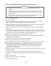
Fig. 13
Adjustment Screw
CCW – Higher
CW – Lower
Top View