


81
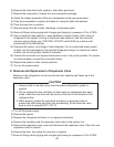
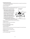
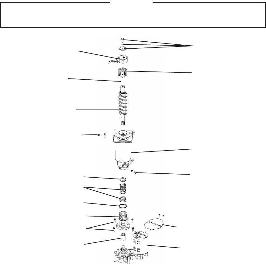
Fig. 11
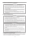
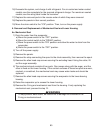
8) Use an electronic leak detector or soap bubbles to check for leaks. Add a trace of
refrigerant to the system (if using an electronic leak detector), and then raise the
pressure using nitrogen gas (140 PSIG). DO NOT use R-404A as a mixture with
pressurized air for leak testing.
9) Evacuate the system, and charge it with refrigerant. For air-cooled and water-cooled
models, see the nameplate for the required refrigerant charge. For remote air-cooled
model, see the rating label inside the icemaker.
10) Attach the expansion valve bulb to the suction line in the same location as the previous
bulb. The bulb should be between the 10 and o'clock position on the tube. Be sure to
secure the bulb with the clamp and holder and to insulate it.
11) Place the expansion valve cover in position.
1) Replace the panels in their correct positions.
13) Turn on the power supply.
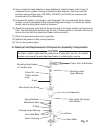
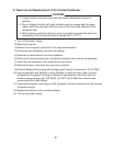
D. Removal and Replacement of Evaporator Assembly Components
CAUTION
On aker models, make sure the cutter pin is in place after service. On cubelet
models, make sure the extruding head heater is installed after service.
Cutter, Bolt, and Washer
Extruding Head
Upper Bearing
Evaporator
Allen Head Cap Screw
with Washer
Allen Head Cap Screw
Housing-Lower Bearing
Gear Motor
Barrier
Spline Coupling
O-Ring
Mechanical Seal
Spring Retainer
Auger
Extruding Head Heater
(-C models only)
Hex Head Bolts
Cutter Pin
(Flaker models
only)