


31
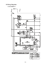
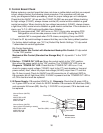
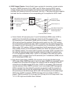
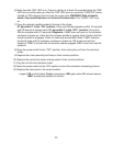
4) 5VDC Output Checks: Control Switch (open contacts for icemaking, closed contacts
for drain), GMPR (terminals 3 & 5), MBC, and F/S. When checking 5VDC control
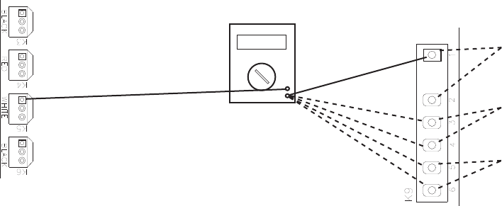
voltage, always place the red positive test lead from the multimeter to the white K5
connector pin closest to the red K4 connector. See Fig. 2. Then place the black negative
test lead from the multimeter to the corresponding pin to complete the 5VDC check.
Red positive test lead to white
K5 connector pin closest to
red K4 connecotor
Fig. 2
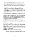
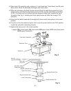
Control Board K9 Connector
Red Positive
Test Lead
Black Negative
Test Lead
Multimeter
a. Control Switch–K9 connector pins #1 and #2 white/black (W/BK) wires: 5VDC is
present from the white K5 connector pin closest to red K4 connector to the
K9 connector pin #1 white/black (W/BK) wire at all times. If 5VDC is not present,
CBisbadandmustbereplaced.Whenthecontrolswitchisinthe"ICE"position,
the control switch contacts are open. 0VDC is present from the white K5 connector
pin closest to red K4 connector to the K9 connector pin #2 white/black (W/BK) wire.
Wheninthe"ICE"position,5VDCispresentfromtheK9connectorpin#1white/
black (W/BK) wire to pin #2 white/black (W/BK) wire. When the control switch is in
the"DRAIN"position,thecontrolswitchcontactsareclosed.5VDCispresentfrom
the white K5 connector pin closest to red K4 connector to the K9 connector pins
#1 or #2 white/black (W/BK) wires. If 5VDC is not present CB is bad and must be
replaced. 0VDC is present from the K9 connector pin #1 white/black (W/BK) wire to
pin #2 white/black (W/BK) wire.
b. Gear Motor Protect Relay (GMPR)–K9 connector pins #5 and #6 white/orange
(WO) wires: When GMPR terminals 3 and 4 are open (GMPR de-energized), 5VDC
is present from the white K5 connector pin closest to red K4 connector to the K9
connector pin #5 white/orange (W/O) wire. If 5VDC is not present, CB is bad and
must be replaced. When GMPR terminals 3 and 4 are closed (GMPR energized),
5VDC is present from the white K5 connector pin closest to red K4 connector to
the K9 connector pins #5 and #6 white/orange (W/O) wires. Also check from the
K9 connector pin #5 white/orange (W/O) wire to K9 connector pin #6 white/orange
(W/O) wire. If 0VDC is present, GMPR terminals 3 & 5 are closed. If 5VDC is
present, GMPR terminals 3 & 5 are open and CB may be in an 8-beep alarm. See
"II.C.2.LEDLightsandAudibleAlarmSafeties."
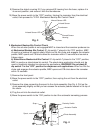
5VDC
Control Switch
white/black (W/BK)
Yellow Jumper (Y)
Gear Motor Protect Relay
(terminals #3 and #5)
white/orange (W/O)