


3
CONTENTS
I. Specications ..................................................................................................................... 5
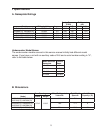
A. Nameplate Ratings ....................................................................................................... 5
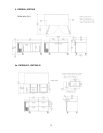
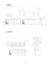
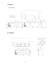
B. Dimensions ................................................................................................................... 5
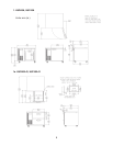
1. HUR40A, HUF40A .................................................................................................. 6
1a. HUR40A-D, HUF40A-D ......................................................................................... 6
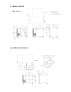
. HWR40A, HWF40A ................................................................................................. 7
a. HWR40A-D, HWF40A-D ....................................................................................... 7
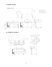
3. HUR68A, HUF68A .................................................................................................. 8
3a. HUR68A-D, HUF68A-D ......................................................................................... 8
4. HWR68A, HWF68A ................................................................................................. 9
4a. HWR68A-D, HWF68A-D ....................................................................................... 9
5. HUR96A ................................................................................................................ 10
5a. HUR96A-D .......................................................................................................... 10
6. HWR96A ............................................................................................................... 11
6a. HWR96A-D ......................................................................................................... 11
II. General Information ........................................................................................................ 1
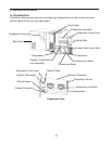
A. Construction ................................................................................................................ 1
B. Sequence of Operation and Timing Charts ................................................................ 13
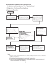
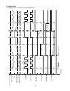
1. Refrigerators – Continuous Operating Mode ........................................................ 13
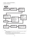
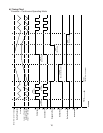
. Freezers – Continuous Operating Mode ............................................................. 15
3. Refrigerators – Energy Saving Operating Mode .................................................. 17
4. Freezers – Energy Saving Operating Mode ......................................................... 19
C. Control Board ............................................................................................................. 1
1. Start-Up Delay ....................................................................................................... 1
. Control Board Layout ............................................................................................
D. Settings and Diagnostics ............................................................................................ 3
1. Gaining Access to Settings and Diagnostics ......................................................... 3
. Temperature Display ............................................................................................. 4
a) Switching the Display Between Fahrenheit and Celsius (F5) .......................... 4
b) Adjusting the Setpoint Temperature ................................................................ 4
c) Cabinet Temperature Correction (calibration factor) ........................................ 5
3. Settings and Diagnostics Menu ............................................................................. 6
a) Defrost Interval (F0) ......................................................................................... 7
b) Defrost Termination Temperature (F1) ............................................................ 7
c) Setpoint Temperature Differential (F) ............................................................ 8
d) High Temperature Alarm Delay Time (F3) ....................................................... 9
e) Low Temperature Alarm Delay Time (F4) ....................................................... 9
f) Temperature Display Scale (F5) ....................................................................... 30
g) Alarm History (F6) ............................................................................................ 30
h) Compressor Run Time (F7) ............................................................................. 31
Please review this manual. It should be read carefully before the unit is serviced or
maintenance operations are performed. Only qualied service technicians should service
and maintain the unit. This manual should be made available to the technician prior to
service or maintenance.