


45
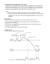
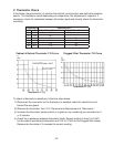
C. Thermistor Check
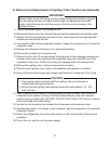
A thermistor (semiconductor) is used for the cabinet control sensor and defrost termination
sensor. The resistance varies depending on temperature. No adjustment is required. If
necessary, check for resistance between thermistor leads and visually check the thermistor
mounting.
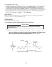
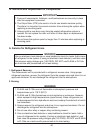
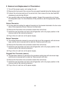
Clogged Filter Thermistor T-R Curve
Cabinet & Defrost Thermistor T-R Curve
To check a thermistor's resistance, follow the steps below.
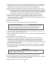
1) Disconnect the connector for the thermistor in question under the control box and
behind the wire guard.
) Remove the thermistor. See "IV.F. Removal and Replacement of Thermistors."
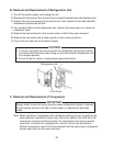
3) Immerse the thermistor sensor portion in a glass or cup containing ice and water for
or 3 minutes.
4) Check for a resistance between thermistor leads. Normal reading is from 5 to 6.5kΩ
for the cabinet and defrost thermistors and 145 to 175kΩ for the clogged lter sensor.
Replace the thermistor if it exceeds the normal reading.
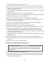
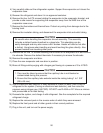
Temperature Resistance (kΩ)
°F °C Cabinet/Defrost Thermistors Clogged Filter Thermistor
0 -17.8 14. -
10 -1. 10.7 -
3
0.0 6.0 160
50 10.0 3.9 100
70 1.1 .5 59
90 3. 1.6 36
Temperature °F (°C)
Temperature °F (°C)