


12
B. Sequence of Operation
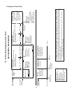
1. Sequence Cycles and Shutdown
The steps in the sequence are as outlined below. When power is supplied and BC is
closed, CB red "POWER OK" LED comes on. There is a 5-second delay before startup.
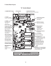
Note that the order of the LEDs from the outer edge of CB is 1, 4, 3, 2.
a) 1-Minute Fill Cycle
LED 4 is on. WV energizes and the 1-minute ll cycle begins. After 1 minute, CB checks
for a closed F/S. If F/S is closed, the harvest cycle begins. If not, WV remains energized
through additional 1-minute ll cycles until water enters the tank and closes F/S. This
serves as a low water safety to protect PM.
b) Initial Harvest Cycle
LEDs 1, 4, and 2 are on. WV remains energized, Comp, FMR, and HGV energize.
CBmonitors the warming of the evaporator via the thermistor located on the suction line.
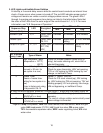
When the thermistor warms to 48°F (9°C), CB reads a 3.9 kΩ signal from the thermistor
and turns harvest termination over to the harvest timer (S4 dip switch 1 & 2) which is
factory set for normal conditions. The harvest timer has settings of 60, 90, 120, and 180
seconds. For details, see "II.C.4.b) Harvest Timer (S4 Dip Switch 1 & 2)." When the
harvest timer terminates, the harvest cycle is complete. At the end of harvest, CB checks
the position of F/S and proceeds to the next cycle if it is closed or calls for a 1-minute ll
cycle if it is open. The minimum total time allowed by CB for a complete harvest cycle is
2minutes. WV is energized during harvest for a maximum of 6 minutes or the length of
harvest, whichever is shorter.
c) Freeze Cycle
LED 1 is on. Comp and FMR remain energized. PM and LLV energize. HGV and WV
de-energize. For the rst 5 minutes, CB will not accept a signal from F/S. This 5-minute
minimum freeze time is short cycle protection for Comp. At the end of 5minutes, F/S
assumes control of freeze termination. As ice builds on the evaporator, the water level
in the tank lowers. The freeze cycle continues until F/S opens, then CB terminates the
freeze cycle.
d) Pump-Out Cycle
LEDs 1, 3, and 2 are on. LED 4 is on when S4 dip switch 3 & 4 are set to 3 off and 4on.
Comp and FMR remain energized. HGV energizes, LLV de-energizes. WV energizes
if S4 dip switch 3 & 4 are set to 3 off and 4 on. PM stops for 2 seconds then reverses,
taking water from the bottom of the tank and forcing pressure against the check valve
seat allowing water to go through the check valve and down the drain. At the same time,
water ows through the small F/S tube to power ush F/S. When the pump-out timer (S4
dip switch 3 & 4) terminates, pump-out is complete.
The rst pump-out occurs after the rst freeze cycle and every cycle thereafter. The
pump-out frequency control is factory set to drain the water tank every cycle, and
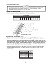
generally no adjustment is required. The pump-out frequency control (S4 dip switch 5
& 6) can be set to have a pump out occur every cycle, or every 2, 5, or 10 cycles. For
details, see "II.C.4.d) Pump-Out Frequency Control (S4 Dip Switch 5& 6)."