


45
4) Close the low-side valve and high-side valve on the gauge manifold.
5) Disconnect the gauge manifold hose from the vacuum pump and attach it to a
refrigerant service cylinder. Remember to loosen the connection and purge the air
from the hose. For water-cooled model, see the nameplate for the required refrigerant
charge. For remote air-cooled model, see the rating label inside the icemaker. Hoshizaki
recommends only virgin refrigerant or reclaimed refrigerant which meets ARI Standard
700 (latest edition) be used.
6) A liquid charge is required when charging an R-404A system (to prevent fractionation).
Place the service cylinder on the scales; if the service cylinder is not equipped with
a dip tube, invert the service cylinder, then place it on the scales. Open the high-side
valve on the gauge manifold.
7) Allow the system to charge with liquid until the proper charge weight is met.
8) If necessary, add any remaining charge to the system through the low-side.
CAUTION! To prevent compressor damage, use a throttling valve or liquid
dispensing device to add the remaining liquid charge through the low-side
service valve with the unit running.
9) Close the service valves, then close the gauge manifold valves and disconnect the
hoses.
10) Cap the service valves to prevent a possible leak.
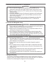
B. Removal and Replacement of Compressor
CAUTION
1. Always install a new drier every time the sealed refrigeration system is
opened.
2. Do not replace the drier until after all other repair or replacement has been
made. Install the new drier with the arrow on the drier in the direction of the
refrigerant ow.
3. When brazing, protect the drier by using a wet cloth to prevent the drier from
overheating. Do not allow the drier to exceed 250°F (121°C).
1) Turn off the power supply.
2) Remove the panels.
3) Recover the refrigerant and store it in an approved container.
4) Remove the terminal cover on the compressor and disconnect the compressor wiring.
On remote air-cooled model, disconnect the crankcase heater.
5) Remove the hold-down bolts, washers, and rubber grommets.
6) Remove the discharge and suction pipes.
7) Remove the compressor. Unpack the new compressor package.
8) Attach the rubber grommets of the prior compressor.
9) Place the compressor in position and secure it using the bolts and washers.