


29
3) Press the "SERVICE 2" button to lower freeze cycle termination temperature setting
(Control Board Setting 2). Temperature setting lowers in .5°C increments. The "." in the
lower, right corner of the display indicates .5°C. Default is -18.5°C. NOTICE! Do not
decrease dimple size below 3/16" (5 mm).
4) Once the display returns to "on" (20 seconds), the new setting is saved.
2. Ice Clarity
In hard water conditions, white ice may be produced. In such cases, install a water lter
and/or water softener, then follow the instructions below.
1) Move the control switch to the "OFF" position, then turn off the power supply.
2) Remove the front panel.
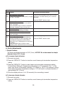
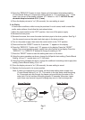
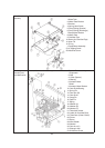
3) Remove the screw, then move the water tank drain pipe to the drain position. See Fig. 2.
Use the screw to secure the water tank drain pipe in the drain position.
4) Turn on the power supply, then move the control switch to the "ICE" position.
5) Press and hold the "RESET" button for 3 seconds. "1" appears in the display.
6) Press the "SERVICE 1" button until "12" appears in the display. Press the "RESET"
button. The current icemaking water supply time value ashes in the display. Press the
"SERVICE 1" or "SERVICE 2" buttons to change the setting to "60".
7) Press the "RESET" button to save the setting and return to the menu.
8) Using the same procedure as above, change the full/partial drain setting (Control Board
Setting 14) from "1" (partial drain) to "0" (full drain).
9) Using the same procedure as above, change the additional icemaking water supply time
setting (Control Board Setting 15) to "44".
10) Once the display returns to "on" (20 seconds), the new setting is saved.
11) Replace the front panel in its correct position.
Note: If white ice continues to be an issue, set hard water setting water supply time
(Control Board Setting 61) to "15". This results in the inlet water valve energizing
for 15 seconds part way through the freeze cycle and diluting the water in the
water tank. Do not increase this setting beyond 15 seconds; otherwise, freeze
cycle times may become long and bridging may occur in the ice storage bin.
Fig. 2
Normal Position
Drain Position
Screw
Water Tank Drain Pipe