


32
5) Disconnect the gauge manifold hose from the vacuum pump and attach it to a
refrigerant service cylinder. Remember to loosen the connection and purge the air
from the hose. For the required refrigerant charge, see the nameplate. Hoshizaki
recommends only virgin refrigerant or reclaimed refrigerant which meets ARI Standard
700 (latest edition) be used.
6) A liquid charge is required when charging an R-404A system (to prevent fractionation).
Place the service cylinder on the scales; if the service cylinder is not equipped with
a dip tube, invert the service cylinder, then place it on the scales. Open the high-side
valve on the gauge manifold.
7) Allow the system to charge with liquid until the proper charge weight is met.
8) If necessary, add any remaining charge to the system through the low-side.
NOTICE!To prevent compressor damage, use a throttling valve or liquid
dispensing device to add the remaining liquid charge through the low-side
refrigerant access valve with the icemaker running.
9) Close the high and low-side gauge manifold valves, then disconnect the gauge manifold
hoses.
10) Cap the refrigerant access valves to prevent a possible leak.
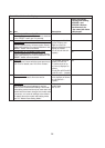
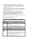
B. Component Service Information
NOTICE
When replacing a component listed below, see the notes to help ensure proper
operation.
Component Notes
Compressor Install a new start capacitor, run capacitor, and start relay.
Thermostatic
Expansion Valve
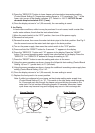
• Attach the thermostatic expansion valve bulb to the suction line in the same location
as the previous bulb.
• The bulb should be between the 10 and 2 o'clock positions on the tube.
• Secure the bulb with the clamp and holder, then insulate it.
Hot Gas Valve • Replace the strainer if applicable.
• Use copper tube of the same diameter and length when replacing valve lines.
Fan Motor Install a new capacitor.
Pump Motor Install a new capacitor.
Actuator Motor Install a new capacitor.
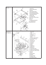
Evaporator
(Cube Control)
Thermistor
• Attach the new thermistor to the same location on the evaporator as the previous
thermistor.
• Smoothly ll the recessed area of the thermistor holder with high thermal conductive
type sealant. Hoshizaki America part number 4A0683-01 (Silicone Heat Sink
Compound 10-8108 manufactured by GC Electronics), KE-4560 RTV (manufactured
by ShinEtsu Silicones), or equivalent are recommended.
• Attach the new thermistor in position on the evaporator and press down the
thermistor holder over the thermistor.
• Be very careful to prevent damage to the leads.