


GB
7
PLEASE PHONE US TO REGISTER YOUR APPLIANCE AND ACTIVATE YOUR PARTS GUARANTEE ON 08448 24 24 24
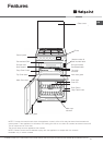
Installation
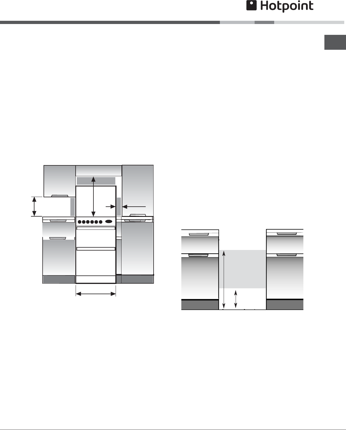
SPACE FOR FIXING
The cooker can be close fitted below hotplate level.
This requires a minimum distance of 600mm between
cupboard units of hotplate height.
When installing next to a tall cupboard, partition or
wall, for a minimum distance of 400mm above hotplate
level, allow a side clearance of at least 65mm.
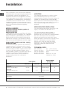
The diagram below illustrates the minimum
clearance between the cooker and adjacent walls,
cupboards etc.
The wall behind the cooker, 50mm below and 450mm
above, and the width of the cooker, must be a non-
combustible material such as ceramic wall tiles.
If the cooker is to be fitted close to a corner on the
left hand side, ensure that there is a clearance of at
least 50mm to allow the main oven door to open fully
for when removing oven shelves.
65 mm Min
840 mm Min
400 mm Min
600 mm Min
750mm Min
COOKER HOODS
If a cooker hood is to be installed, refer to the
cooker hood manufacturers' instructions regarding
fixing height.
UNPACKING THE COOKER
Unpack the components from inside the grill and
oven.
Check that the following parts are present:
Grill pan and grid Aluminium burner bodies(4)
Baking dish Pan supports
Main oven shelves (2) Enamelled burner caps (5)
Top oven/grill shelf (1) Literature
LEVELLING
Four skid feet are fitted which can be adjusted up or
down to level the cooker.
CONVERSION FOR USE ON BUTANE
(G30) OR PROPANE (G31)
Each burner requires the injector to be replaced and
bypass screws adjusted or replaced as follows:
1. Remove the loose hotplate burner parts.
2. Using a 7mm socket, replace the hotplate injectors
as appropriate (see table on previous page).
3. Re-position the loose burner parts.
4. Carefully pull off the hotplate control knobs.
5. Using a narrow flat bladed screwdriver rotate the
bypass screws fully clockwise. The hotplate tap
bypass screws are located down the centre of the
spindle.
6. Re-assemble the control panel parts.
7. Secure the self-adhesive LPG conversion label over
the gas details on the data badge.
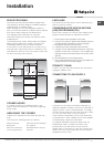
STABILITY CHAIN
A hole in the gas inlet valve bracket can be used to
engage a stability chain.
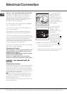
CONNECTING TO GAS SUPPLY
300
670
Connection to the cooker should be made with an
approved appliance flexible connection to BS 669. A
length of 0.9 to 1.25m is recommended. The length
of hose chosen should be such that when the cooker
is in situ, the hose does not touch the floor.
Those cookers converted to use on LPG should be
connected with a hose suitable for LPG and capable
of withstanding a pressure of 50 mbar.
An adaptor backplate should be fitted within the
shaded area shown, to allow the cooker to be
pushed fully to the wall and to ensure that the
flexible hose is only likely to come into contact with
areas at the rear of the cooker that do not exceed a
temperature rise of 70°C.