


Continuous Flow Icemaker Service Manual
Publication Number: 630460174SER - 12 - © 2004-2005, IMI Cornelius Inc.
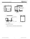
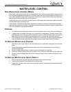
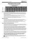
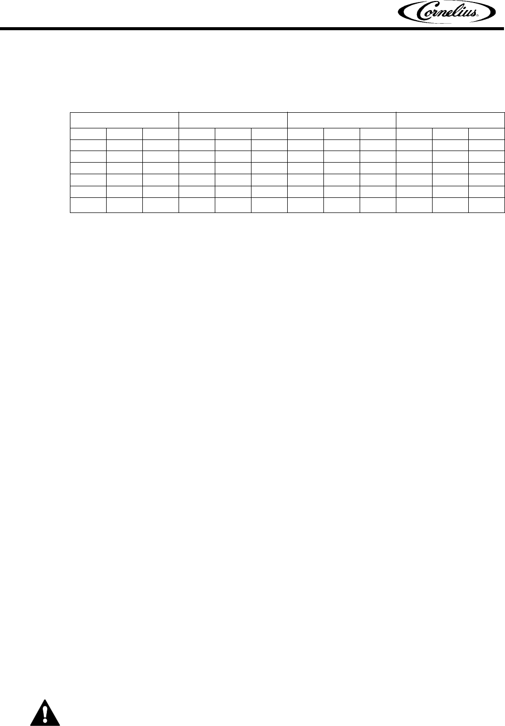
REFRIGERATION SYSTEM
Thermostatic Expansion Valve NO Adjustment.
+/- 10 lbs. Discharge Pressure
Water Temperature
REFRIGERATION SYSTEM ADJUSTMENTS
A complete understanding of the icemaker and hermetic refrigeration system is necessary before any
adjustments are made. The refrigeration technician must use high and low side pressure readings, water
and air temperatures, plus general conditions of cleanliness to assess the refrigeration system status
when making any adjustments.
All icemaker products are tested and adjusted at the factory prior to shipment where the ambient
temperature ranges from 65° to 90°F, depending on the season of the year.
Whenever a new icemaker product is initially installed and started–up, it is imperative that the start–up
operation make the following checks and/or readjustments for local conditions.
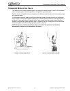
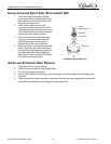
EXPANSION VALVE
You will find a thermostatic expansion valve on icemakers, which is used to control the amount of
refrigerant flowing through the evaporator. Improperly installed or defective expansion valves may cause
low production, soft ice, squeaking from evaporator and excessive load inside evaporator.
By using general refrigeration system troubleshooting along with the pressure charts you can easily
determine whether or not the expansion valve is working properly.
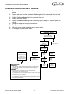
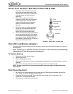
ADJUSTMENT AND TROUBLESHOOTING
When troubleshooting the expansion valve you must first be sure you have adequate water flowing into
evaporator, a clean condenser, unit is properly ventilated, and system is properly charged and free from
any restrictions. Also be sure compressor is operating properly.
Second, take reservoir water temperature and air temperature from condenser inlet and determine at
what pressure unit should be running. Machines are equipped with thermostatic valves, there is NO
adjustment. If correct pressure cannot be obtained, first be sure system has time to stabilize 10–15
minutes. Second, be sure sensing bulb is located at 12:00 position on outlet side of evaporator about 3–4
inches away from evaporator and be sure to insulate well and clamp tightly to tubing. If system pressures
are still not adequate, take a second water and air temperature reading and go over other parts of system
for possible problems. If proper charge is questionable evacuate and recharge to nameplate and leak
check. If valve still malfunctions replace valve.
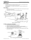
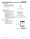
When replacing valve be sure to bleed refrigerant gas from low side port so as not to lose refrigerant oil.
Use general refrigerant system practices when replacing and recharging unit. After new valve is in place,
go through previous monitored adjustments and troubleshooting to be sure valve is functioning properly.
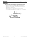
NOTE: Units with thermostatic expansion valve—valve is located on bottom refrigerant line.
Sensing bulb is located on top refrigerant line. On water cooled units adjust condenser
modulating valve before troubleshooting expansion valve.
CAUTION: Very High discharge pressure is present in system. Quick disconnects on you gauges
will minimize danger and loss of refrigerant. Comply with federal regulations for reclaiming
refrigerant.
WCC 500 WCC 700 WCC 1000 WCC 2200
40° 65° 90° 50° 65° 90° 50° 65° 90° 50° 65° 90°
50° 162 166 168 60° 177 180 60° 171 172 60° 201 203
60° 188 ‘92 194 70° 205 208 70° 199 200 70° 219 220
70° 214 218 220 80° 233 236 80° 227 228 80° 253 254
80° 245 249 251 90° 269 272 90° 263 264 90° 298 300
90° 275 279 281 100° 304 307 100° 298 299 100° 330 332
100° 309 313 315 328 334 340 324 328 332 362 364 366
Air Temperature