


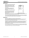
Continuous Flow Icemaker Service Manual
© 2004-2005, IMI Cornelius Inc. - 5 - Publication Number: 630460174SER
BIN CONTROL
GEARMOTOR
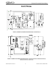
The gearmotor is equipped with a start relay and a manual reset overload.
When current is applied, the relay energizes and completes the circuit to the start winding. The motor
reaches a predetermined speed and the relay drops out, disconnecting the start winding. The run
winding remains in the circuit as long as current is applied.
The purpose of the overload is to automatically shut off the motor in the event of a mechanical bind of the
transmission, an overload condition within the evaporator or an electrical malfunction. It does this by
sensing amperage draw. If the motor stalls the start relay would energize and stay energized. The
amperage would surge 5 to 6 times greater than the normal draw. In this event the overload would shut
off the transmission in 4 to 8 seconds.
If the motor is subjected to an abnormal load, but does not reach a stall condition, the overload will react,
but over a greater period of time. The reaction time depends upon the amperage to which it is subjected.
The overload, through the safety circuit, also shuts off the compressor.
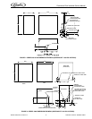
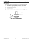
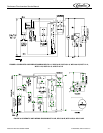
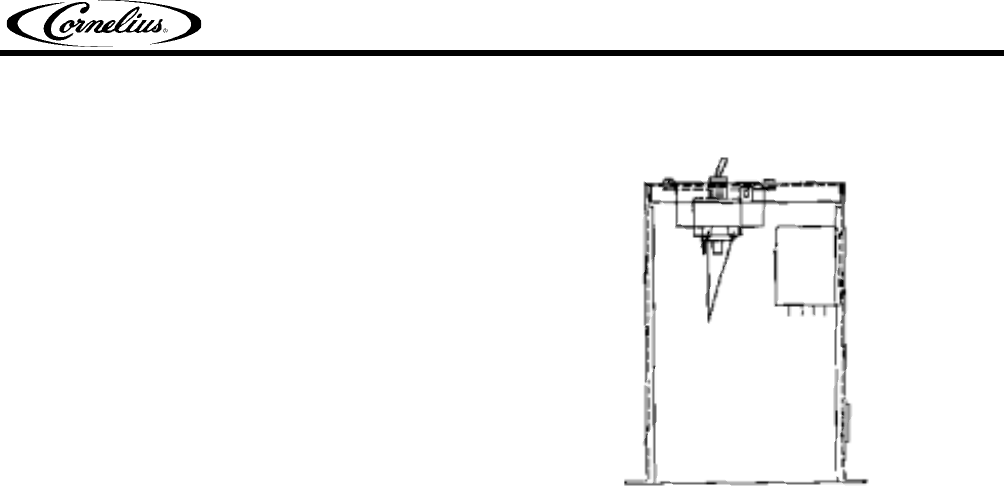
The type of bin control used on all WCC & WCF
Models is an electronic control. The control is
supplied with power to terminals X1 and X2.
Terminals X3 and X4 are a normally closed
switch which open when the thermostat sensor
bulb senses ice.
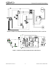
The sensing element is located in a 5/16”
stainless steel tube which hangs from the
dispense tray cover down through the center of
the drop tube.
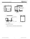
To test switch, start the icemaker and block the
outlet tube. When the ice fills the drop tube
about 1/2 full the icemaker should shut off.
When tube is cleared the ice maker should
restart within 5 min.
FIGURE 4. BIN CONTROL SWITCH
The Bin control is in electrical series with coil on antifreeze relay along with the low water safety. If unit is
water cooled, the condenser high pressure cut out is also in series.
The Control Switch is held in place inside electrical box by 2 screws. The Control bulb is in the drop tube.
It can be removed by pulling the cable located on the top of the dispense tray cover. When replacing the
sensor make sure the bulb is inserted to the bottom of the thermostat well.
BIN CONTROL
SWITCH TERMINALS