


UC100 Installation Manual
Publication Number: 621054211INS - 4 - © 2008, IMI Cornelius Inc.
INSTALLATION INSTRUCTIONS
IMPORTANT: It is the responsibility of the Installer to ensure that the water supply to the
dispensing equipment is provided with protection against backflow by an air gap as defined in
ANSI/ASME A112. 1.2–1979; or an approved vacuum breaker or other such method as proved
effective by test.
1. Locate the dispenser indoors on a level counter top.
A. Caster Option
Unpack the four (4) casters and install them into the threaded holes provided in the bottom of the
unit. The installer must provide flexibility in the product and utility supply to permit shifting the
position of the dispenser sufficiently to clean the area beneath it.
B. Counter Mounting
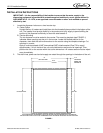
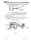
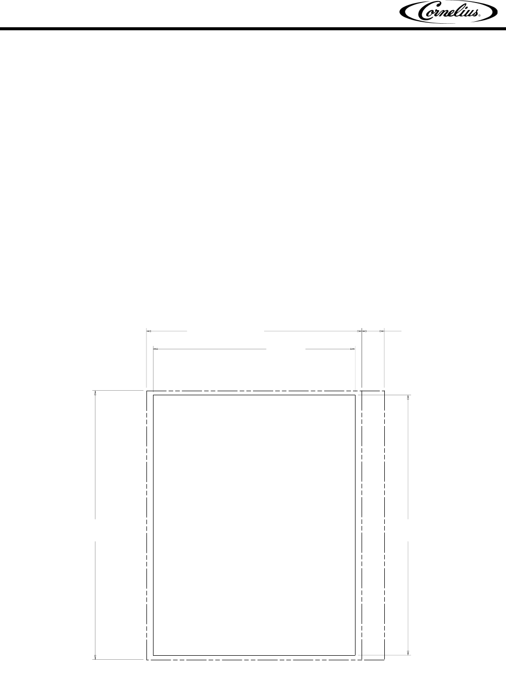
The ice dispenser must be sealed to the counter. The mounting template (see FIGURE 1)
indicates where openings can be cut in the counter. Locate the desired position for the
dispenser, then mark the outline dimensions on the counter using the template drawings. Cut
openings in counter.
Apply a continuous bead of NSF International (NSF) silastic sealant (Dow 732 or equal)
approximately 1/4-inch inside of the unit outline dimensions and around all openings. Then,
position the unit on the counter within the outline dimensions. All excess sealant must be wiped
away immediately.
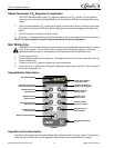
2. The drain lines, power cord and air supply are routed through the openings in the bottom of the unit.
FIGURE 1
CUT OUT
22 1/2
CUT OUT
29
CLEARANCE
NEEDED FOR
OPENING LID
21/2
UNIT FOOT PRINT
24
UNIT FOOT PRINT
30
THIS FIGURE SHOWS THE REQUIRED CUTOUT FOR PLACING THE ICE DISPENSER INTO A COUNTER TOP.
THE SOLID LINE IS THE ACTUAL CUTOUT DIMENSIONS WHILE THE DASHED LINE SHOWS THE UNIT FOOT PRINT