


UC100 Installation Manual
© 2008, IMI Cornelius Inc. - 5 - Publication Number: 621054211INS
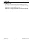
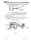
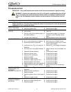
3. The dispenser drain lines must slope a minimum of 1/4” per foot to the floor drain, see FIGURE 2.
Drain lines must be installed to comply with federal, state and local codes. It is required to fully
insulate all drain lines and fittings to prevent condensation from forming!!!
FIGURE 2
If the unit is installed in a: 36” tall counter top, the floor drain must be within 23’ of the dispenser.
34” tall counter top, the floor drain must be within 15’ of the dispenser.
30” tall counter top, the floor drain must be within 1’ of the dispenser.
4. Clean the hopper interior (see CLEANING INSTRUCTIONS in Operator’s Manual).
5. Connect the power cord to a 120 volt, 60 cycle, 15–Amp, 3–wire grounded receptacle.
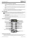
Set Up Supplied Air Compressor
1. Set up and install the air compressor, follow the manufacturer’s installation instructions.
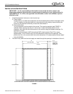
2. Route the 1/4” beverage tube from the air compressor to the air valve solenoid inlet tube connector
on the dispenser.
NOTE: The filter/regulator is preset to 50 psi and should not require adjustment.
FIGURE 3
Drain Line
Dispenser
Drain Point
Horizontal
Reference Line
1/4”
1’
Floor Drain
CLEAR RED TUBE
CLEAR TUBE
E-BOX
FILTER/REGULATOR ASSEMBLY
PRESET TO 50 PSI, NO ADJUSTMENT NEEDED
1/4" TUBE WHIP
(SUPPLIED WITH UNIT)
CUSTOMER CONNECTION
INCOMING SUPPLY SHOULD BE
SET TO 100 PSI
AIR VALVE SOLENOID
AIR CYLINDER
(LOCATED IN
AIR SCHEMATIC
TOWER CLADDING)