


JFT Series Technical Manual 7610-002-77-38
Issued: 03-16-2006 Revised: N/A
15
SECTION 2: INSTALLATION/OPERATION INSTRUCTIONS
INSTALLING THE JFT DISHMACHINE (CONTINUED)
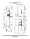
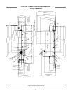
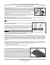
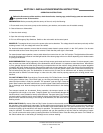
STEAM TRAP CONNECTIONS: There are steam traps provided on the discharge side of all
steam heating devices. A typical unit will have traps on the following: wash section heating
coil outlet, power rinse section heating coil outlet, rinse booster heater outlet, and an option-
al blower dryer section heating coil outlet. All steam traps can be seen by removing all of the
above mentioned sections lower dress panels. The steam traps are 3/4” FNPT and should be
plumbed together to provide condensate return to the building’s boiler system.
PLUMBING CHECK: Slowly turn on the water supply to the machine after the incoming fill
line and the drain line have been installed. Check for any leaks and repair as required. All
leaks must be repaired prior to placing the machine in operation.
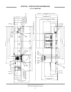
ELECTRICAL POWER CONNECTION: Electrical and grounding connections must comply with the applicable portions of the
National Electrical Code ANSI/NFPA 70 (latest edition) and/or other electrical codes.
Disconnect electrical power supply and place a tag at the disconnect switch to indicate that you are working on the cir-
cuit.
Refer to the data plate for machine operating requirements, machine voltage, total
amperage load and serial number.
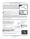
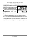
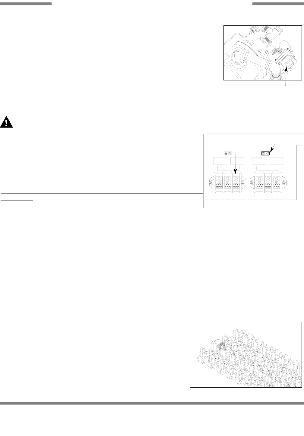
To install the incoming power lines, open the control box. Install conduit into the pre-
punched holes in the top of the control box. Route power wires and connect to power
block and grounding lug. Tighten the connections. It is recommended that “DE-OX”
or another similar anti-oxidation agent be used on all power connections.
Please note that the individual sections require sep
arate incoming power supplies
and services.
Refer to the machine data plate for information related to service cir-
cuit sizing. Ensure that services are labeled correctly. Ensure that service is sized
correctly according to applicable local, state and national codes. Always refer to the
machine data plate to get the total amperage load for each section.
VOLTAGE CHECK: Ensure that the power switch is in the OFF position and apply power to the dishmachine. Check the incom-
ing power at the terminal block and ensure it corresponds to the voltage listed on the data plate. If not, contact a qualified ser-
vice agency to examine the problem. Do not run the dishmachine if the voltage is too high or too low. Shut off the service break-
er(s) and mark as being for the dishmachine. Advise all proper personnel of any problems and of the location of the service
breaker. Close and lock the control box cover until authorized technicians can look at the problem and determine an appropri-
ate solution.
The protective measures must be executed according to the conditions of the local power utilities. All electrical cable connec-
tions are to be provided with marked cables screwed in the electrical switch cabinet, according to the wiring diagram and to be
connected to the respective terminals and contactors. Please check the electrical tension.
a. Check all motors for sense of direction.
b. Retighten all terminal fixing screws before the setting in operation.
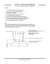
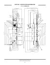
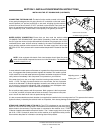
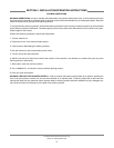
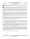
INSTALLATION OF THE MACHINE’S TRANSPORT BELT: The transport belt
is provided in sections of approximately 12 feet. One end of each section will
have the belt rod inserted and the opposing end will have the belt fingers hang-
ing down. To install the belt, stand at the load end section of the dishmachine.
Remove the end cap from one of the rods. Take the belt rod end of one 12 foot
section and place on the top guide rails at the load end. Ensure that the fingers
are pointing upward. Push the section into the machine until the loose finger
end is approximately one foot from the entrance of the machine. The next 12
foot section of the transport belt can then be placed at the load end.
Temporarily remove the belt rod and interlace the fingers of the two belt sec-
tions to conform with the arrangement of all belt fingers. Please refer to the dia-
Steam Trap
Control Box Electrical Connection
Terminal Block
Ground Lug
Transportation Belt