


JFT Series Technical Manual 7610-002-77-38
Issued: 03-16-2006 Revised: N/A
16
SECTION 2: INSTALLATION/OPERATION INSTRUCTIONS
INSTALLING THE JFT DISHMACHINE (CONTINUED)
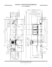
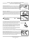
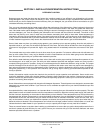
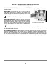
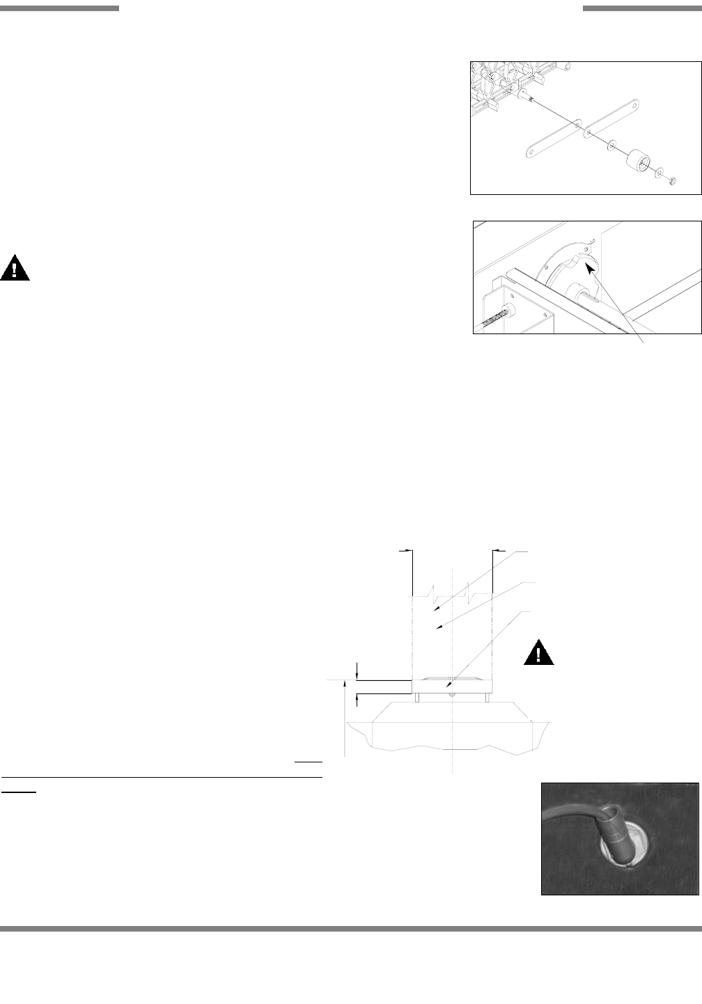
gram to see the order in which the provided washers, wheels, locknuts, and plate
connectors are arranged for proper operation. Continue this process of pulling sec-
tions through and connecting sections until the belt is completely installed. Note:
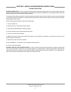
Take care that the belt wheels are guided correctly at the unload section and fall with-
in the depressions on the drive wheels (Please refer to the page entitled “Unload End
Assembly”). The wheels must be placed on top of the lower belt rails before contin-
uing the process. When the lead end of the transport belt returns back to the load
end of the machine, ensure that it will overlap the last section of the belt added.
Remove as many rod sections of either end as to make the connection between both
ends.
Pay attention to the cross-struts of the machine. Be careful to not place fingers
through the belt! Your hand could be injured.
The dishmachine has two transport speeds. The transport speed can be adjust-
ed during operation from low to high or vice versa by adjusting the conveyor speed
switch located on the electrical cabinet.
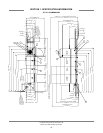
BELT TENSION: It must be possible to lift up the belt in the section of the free feed-
ing or discharge zone by approximately 2” to 4”. The tension station can be adjusted
by loosening the three bolts on each of the two slotted adjusting plates. Pull each plate back until all wheels along the plates
perimeter are firmly touching. Tighten the bolts. Visually inspect the belt for parallelism and ensure the plates are evenly tight-
ened by measuring their distance from the runoff sheet or the end plate. Check tension by pulling the belt off of the top rails by
hand. There should be no greater than a 4” separation. If there is, loosen the slotted adjusting plates, remove one rod section
of the belt and repeat the tensioning process.
INSTALLATION OF DRIVE MOTOR CHAIN: Install chain around large gear. Lift gear motor from bottom to apply tension to
drive springs. Install chain over small gear and release gear motor. Drive springs will automatically tighten chain to it’s proper
tension.
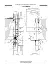
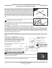
VENTILATION OF DISHMACHINE: The dishmachine
should be located with provisions for venting into an ade-
quate exhaust hood or ventilation system. This is essential
to permit efficient removal of the condensation exhaust.
Ensure that the exhaust system is acceptable in accor-
dance with all applicable codes and standards.
This units covered in this manual have the following
exhaust requirements:
FPM (INDIRECT) 1200
The exhaust system must be sized to handle this volume
for the dishmachine to operate as it was designed to.
ELECTRIC HEAT: The thermostats are factory set. They
should not be adjusted except by an authorized service
agent.
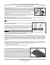
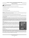
CONNECTION FOR THE DETERGENT SUPPLIER: The detergent connection point is at the rear
of the wash section on the machine.
Chemical feeder equipment must not be mounted inside the main control box. Contact your local
chemical distributor for more information regarding chemical feeders.
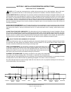
A.F.F.
6'-10"
3" DEEP
18" I.D. SQUARE
CONDENSATE DUCT PAN MOUNTED ON
TOP OF DISHMACHINE ELECTRICAL
SECTION.
CONDENSATE EXHAUST DUCT.
MINIMUM 18" SQUARE (CROSS SECTION 324
SQ INCHES)
PROVIDED BY HVAC CONTRACTOR
CONDENSATE DUCT TO EXTEND
INTO DUCT PAN
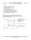
Unload End Assembly - Drive Wheel
Transportation Belt Hardware
NOTE: Damage caused
by steam or moisture
due to improper ventilation
is NOT covered under the
warranty.
Detergent Connection