Section
Description Page
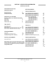
I. Specifications
Operating Capacities 2
Electrical Requirements 3
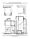
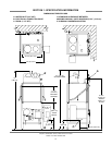
Dimensions Tempstar/Tempstar LT/Tempstar NB (Side Mounted Control Box) 4
Dimensions Tempstar/Tempstar LT/Tempstar NB (Top Mounted Control Box) 5
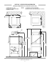
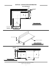
Dimensions Tempstar SDS 6
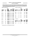
Table Dimensions 7
II. Installation/Operation Instructions
Installation Instructions 9
Electrical Installation Instructions 10
Operation Instructions 11
Detergent Control 12
False Panel Installation 13
III. Preventative Maintenance 15
IV. Troubleshooting Section 17
V. Drawing/Parts Section
Top Mounted Control Box Assembly (Universal Timer) 20
Top Mounted Control Box Assembly (Mechanical Timer) 22
Side Mounted Control Box Assembly 24
SDS Control Box Assembly 26
Hood Assembly 28
Hood Assembly (Bolted Single Support Design) 29
Cantilever Arm/Door Assemblies 30
Tub Assembly 32
Steam Tub Assembly 34
Frame Assembly 36
Rinse Tank Assembly 37
Coil Assembly 38
Incoming Steam Plumbing Assembly 39
Wash Motors 40
Motor & Pump Assembly 41
Wash Heaters/Rinse Heaters 42
Incoming Plumbing/Outlet Plumbing Assembly 43
WPRK Kit Option 44
Tempstar LT & Tempstar NB Incoming Plumbing Assembly 45
Tempstar SDS Incoming Plumbing Assembly 46
3/4” Solenoid Valve & 3/4” NPT Vacuum Breaker Repair Parts Kits 47
Wash and Rinse Arm/Manifold Assemblies 48
Tempstar SDS Dispenser Assembly 50
Safety Door Interlock (SDI)/Exhaust Fan Control/Transformer Mounting Box Components 55
False Panel Installation 56
GO*BOX Kit 57
Drain Quench Assembly 58
TABLE OF CONTENTS
iii


