


26 16023417 ©2004 Maytag Services
Disassembly Procedures
To avoid risk of electrical shock, personal injury, or death:
disconnect electrical and gas supply before servicing.
WARNING!
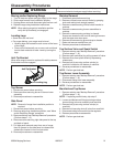
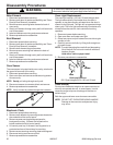
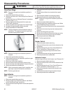
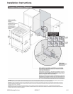
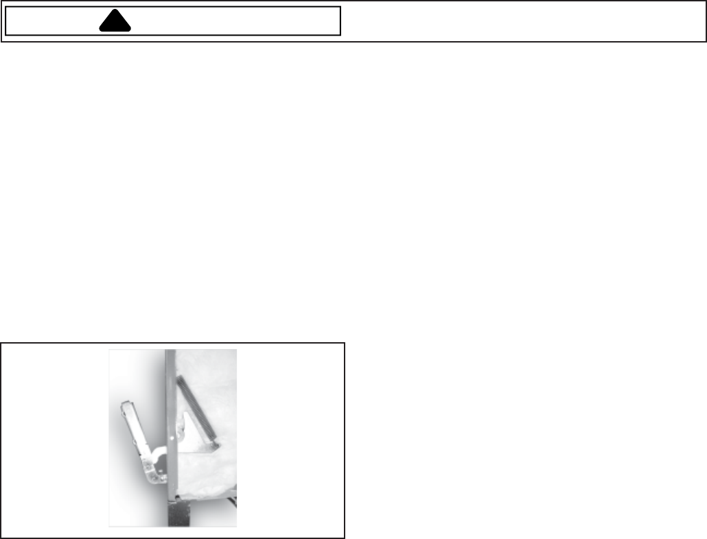
Oven Door Hinge
NOTE: Removal of range from installation position is
required.
1. Disconnect power before servicing.
2. Remove oven door, see "Oven Door(s)-Door Removal"
procedure.
3. Remove maintop, see "Maintop Removal" procedure.
(Perform steps 1 – 6.)
4. Remove appropriate side panel (left or right), see
"Side Panel" procedure.
5. Remove screws securing hinge to front frame flange.
6. Complete hinge assembly may be removed.
7. Reverse procedure to reassemble.
NOTE: The door hinges are colored coded for ease of
installation. The upper spring hook is gold and
the lower spring hook is white.
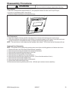
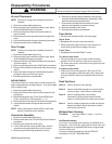
Regulator
NOTE: Removal of range from installation position is
required.
1. Disconnect power before servicing.
2. Slide range forward out of installation position to gain
access to components.
3. Disconnect tubing from regulator.
4. Remove screws securing bracket to back of unit.
5. Remove screws securing regulator to support bracket.
6. Reverse procedures to reassemble.
NOTE: When reconnecting supply line to regulator use
pipe dope compound to seal the connection.
NOTE: Perform gas leak test.
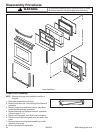
Spark Module
NOTE: Removal of range from installation position is
required.
1. Disconnect power before servicing.
2. Remove range from installation position, see "Move
and/or Replacing Range" procedure.
3. Remove screws securing bottom rear access panel to
chassis.
4. Remove screws securing top rear access panel to
chassis.
5. Disconnect and label wire terminals from spark
module.
6. Remove spark module from secured position.
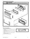
7. Reverse procedures to reassemble.Gas Valve
NOTE: Removal of range from installation position is
required.
1. Disconnect power before servicing.
2. Remove range from installation position, see "Move
and/or Replacing Range" procedure.
3. Remove screws securing bottom rear access panel to
chassis.
4. Remove screws securing top rear access panel to
chassis.
5. Disconnect tubing from gas valve.
6. Disconnect and label wire terminals from gas valve.
7. Remove screws securing gas valve to chassis.
8. Reverse procedures to reassemble.
NOTE: Perform gas leak test.
Rocker Switch
1. Disconnect power before servicing.
2. Remove infinite switch control knobs located on the
backguard.
3. Remove backguard, see "Oven Control/Electronic
Clock" procedures. (Perform steps 1 – 4.)
4. Remove housing securing rocker switch to the
backguard.
5. Label and disconnect wiring and remove switch.
6. Reverse procedures to reassemble.
Indicator Lamps
Indicator lamps include "Hot Surface" and "Element On."
1. Disconnect power before servicing.
2. Remove infinite switch control knobs located on the
backguard.
3. Remove backguard, see "Oven Control/Electronic
Clock" procedures. (Perform steps 1 – 4.)
4. Remove housing securing indicator lamps to the
backguard.
5. Label and disconnect wiring and remove lamps.
6. Reverse procedures to reassemble.