


©2004 Maytag Services 16023417 27
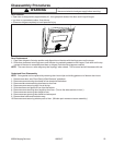
To avoid risk of electrical shock, personal injury, or death:
disconnect electrical and gas supply before servicing.
Disassembly Procedures
WARNING!
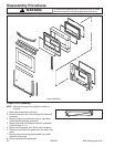
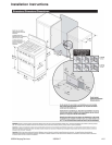
Hi-Limit Thermostat
NOTE: Removal of range from installation position is
required.
1. Disconnect power before servicing.
2. Remove range from installation position, see "Move
and/or Replacing Range" procedure.
3. Remove screws securing main back shield and
remove shield.
4. Remove screws securing thermostat to range main
back.
5. Label and disconnect wiring and remove thermostat.
6. Reverse procedures to reassemble.
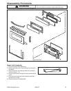
Door Plunger
NOTE: Removal of range from installation position is
required.
1. Disconnect power before servicing.
2. Remove range from installation position, see "Move
and/or Replacing Range" procedure.
3. Remove maintop, see "Maintop Removal" procedure.
(Perform steps 1 – 6.)
4. Remove right side panel, see "Side Panel" procedure.
5. Disconnect and label wire terminals from door plunger
switch.
6. Open oven door and remove screws securing door
plunger to the front of the oven cavity.
7. Reverse procedures to reassemble.
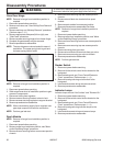
Infinite Switch
The infinite switch is a rotary switch, which controls the
power dissipated by a heating element. They are located
on the control panel.
1. Disconnect power before servicing.
2. Remove infinite switch control knobs located on the
backguard.
3. Remove backguard, see "Oven Control/Electronic
Clock" procedures. (Perform steps 1 – 4.)
4. Remove screws securing infinite switch to backguard.
5. Label and disconnect wiring and remove infinite
switch.
NOTE: When replacing an infinite switch, ensure the
switch is matched to the element.
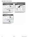
Convection Assembly
1. Disconnect power before servicing.
2. Remove oven door, see "Oven Door(s)-Door Removal"
procedure.
3. Remove oven racks from oven cavity.
4. From inside the oven cavity (center-rear), remove
screws securing assembly shroud or ring-cover.
5. Remove screws securing assembly to cavity.
6. Remove by gently rotating assembly until enough
clearance is established between assembly, cavity
wall and wire terminals/connectors.
7. Disconnect and label wire terminals from heat
element and assembly (connector block).
8. Remove assembly from cavity.
9. Reverse procedures to reassemble.
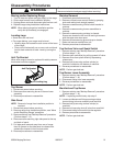
Oven Racks
• All racks are designed with a lock-stop edge.
Upper Oven
• Equipped with one rack and rack position.
• When pulling the upper oven rack out to remove or
check food, grasp the front edge of the rack.
Lower Oven
• Equipped with two RollerGlide™ racks.
To remove oven racks:
• Pull rack straight out until it stops at the lock-stop
position; lift up on the front of the rack and pull out.
• For lower oven racks, pull both the rack glide and rack
base out together.
To replace oven racks:
• Place rack on the rack support in the oven; tilt the
front end up slightly; slide rack back until it clears the
lock stop position; lower front and slide back into the
oven.
Rack Positions
Rack 4: Use for some two-rack baking.
Rack 3: Use for most baked goods on a cookie sheet
or jelly roll pan, layer cakes or frozen pies.
Rack 2: Use for roasting small cuts of meat,
casseroles, baking loaves of bread, bundt
cakes or custard pies and cakes and cookies.
Rack 1: Use for roasting large cuts of meat and poultry,
dessert souffles or angel food cake, and two-
rack baking of biscuits.
Multiple Rack Cooking:
Two Rack: Use rack position 1 and 4, 1 and 5 or
2 and 5.
Half Rack Accessory
A half rack, to increase oven capacity, is available as an
accessory. It fits in the left, upper portion of the oven and
provides space for a vegetable dish when a large roaster
is on the lower rack.
Contact your Maytag dealer for the "HALFRACK"
Accessory Kit or call 1-800-688-8408.