


6
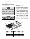
Important Installation Suggestions
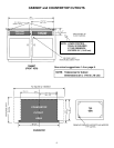
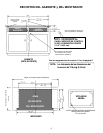
1. Chamfer all exposed edges of decorative laminate to
prevent damage from chipping.
2. Radius corners of cutout and file to insure smooth
edges and prevent corner cracking.
3. Rough edges, inside corners which have not been
rounded and forced fits can contribute to cracking of the
countertop laminate.
4. Countertop must be supported within 3 of cutout.
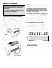
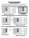
On any burner, closing the air shutter too far will
cause the flame to become soft and yellow tipped.
Opening the air shutter too wide will cause the flame
to blow away from the burner ports. Proper adjustment
will produce a sharp, clearly defined, even blue flame.
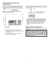
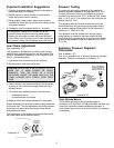
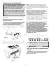
Low Flame Adjustment
(See Illustration “C”)
This appliance is shipped from the factory with low and
medium flame settings adjusted for use with Natural Gas.
If further adjustment is necessary, or to re-adjust for use
with LP, proceed as follows:
1. Light burner and set control knob for low flame.
2. Remove control knob from valve stem.
CAUTION: NEVER USE A METAL BLADE TO PRY
KNOB OFF. IF KNOB CANNOT BE EASILY
REMOVED, TUCK THE FOLDS OF A CLOTH
DISHTOWEL UNDER THE KNOB AND PULL THE
TOWEL UPWARD WITH STEADY, EVEN PRES-
SURE.
3. Insert a slender, thin-blade screwdriver into the recess
at center of valve stem and engage blade with slot in
adjusting screw.
4. Turn center stem adjusting screw to set flame size.
...clockwisetoreduce.
...counterclockwise to increase.
5. Replace control knob when adjustment is completed.
P r oper adjus t m ent will pr oduc e a s t able, s t eady blue f lam e
of minimum size. The final adjustment should be checked
by turning knob from high to low several times without
extinguishing the flame.
This adjustment, at low setting, will automatically provide
the proper flame size at medium setting.
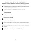
Pressure Testing
The maximum gas supply pressure for the appliance
pressure regulator supplied on this appliance is 14 W.C.
The test pressure for checking this appliance pressure
regulator must be at least 6 W.C. for Natural Gas, and at
least 11 W.C. for LP. It is shipped from the factory set for
Natural Gas at 5 W.C.
This appliance and its individual shutoff valve must be
disconnected from the gas supply piping system during
any pressure testing of that system at test pressures in
excess of 1/2 PSIG (3.5 k Pa).
This appliance must be isolated from the gas supply
piping system by closing its individual manual shutoff
valve during any pressure testing of the gas supply piping
system at test pressures equal to or less than 1/2 PSIG
(3.5 k Pa).
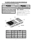
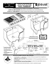
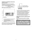
Appliance Pressure Regulator
Conversion
(See Illustration “D”)
This unit is supplied with a Maxitrol Appliance Pressure
Regulator. Follow the instructions in illustration “D”.
Illustration “D”
NAT
LP
CONVERTER
CAP
AND PIN
MAXITROL APPLIANCE PRESSURE REGULATOR
NAT LP
APPLY
SIDEWARD
FINGER
PRESSURE TO
REMOVE PIN
FROM CAP
APPLY DOWNWARD
FINGER PRESSURE
AT DISC EDGES TO
REPLACE PIN IN CAP
Illustration “C”
High Altitude Notice
The specified gas burner ratings typically apply to
elevations up to 2000 feet. For higher altitudes, the rates may
need to be reduced to achieve satisfactory operation. A
local certified gas servicer will be able to advise if a reduction
is necessary.