


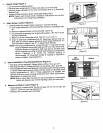

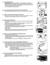
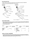
11. WallVentCutout (Figure11)
oceeveasuserr.uareusua0 c°si
center to center. II _- _ . WALLSTUD
• Willtheventductbe6" (15.24cm) roundthroughthewallor3-1/4" x 10"
(8.26cmx 25.4cm) rectangle,verticatlyinsidethe wall? /"
• See DuctingInstructionsfor rearduct insidethe wall. Note: Cutoutin the
wall must clear3-1/4" x 10" (8.26cm x 25.4 cm)transition elbow.
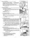
• Locate the closest stud to your proposed vent hole location. Use the r_ (/_._
followingchartto figurethe "X"dimension.Seethe illustrationforthe other
dimensions.
VERTICALDUCTINSIDEWALL . . .
6" Round(15.24cm) 3-1/4"x 10" (Figure11)
(8.26cmx25.4cm)
THROUGH THROUGH
"X"MINIMUM 4" (10.16cm) 6"(15.24cm) OUTSIDEWALL THEFLOOR
I" )_
12.54cm
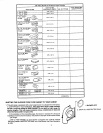
• A 1" (2.54cm)lengthof duct mustprotrudethroughthewallforconnection _- --"=""_._"D'U'_Th
tOthe blower. (_
NOTE:Optimum vent location is 11" to 17" from edge of cabinet. Vents _1_] J'J_fT
locatedfrom 9-3/8"to 11"will requireunitto be raisedover blowerfor
_ / j f j _r _.-iJ / _,3rf / _ _ _ Jrf Jttf n_f IF •
installation. METALJOUCTDucTTAPE I DUCT_TAPE
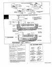
12. InstallBlower (PriorTo InstallingRange) (Figure12) (Figure 12)
• Refertoyourvent plan. it maybe desirableto attachpart ofthe ducting
to theblowerbeforeit is installed. L'IOCATEELECTRICA_'L
• Positiontheblower(seeillustration)and attachittothefloorwithat least POWERIN
two (2)screws: SHADEDAREA I
• Applyducttapearoundblowerexhaust/ductjoint.
I
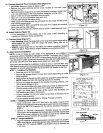
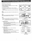
,3. InstallElectrical(Figure 13)
• Note:Observealllocalelectricalcodes.
• CAUTION:Makesure powerto cable is OFF. _
• Locatetheelectricpowersupplyinthefloor orwall, anyplaceinthe shaded /.-_, 5FEETOF
areawhichwillclearthe blower. _) ELECTRICAL CABLE
• DirectConnect.Pullthrough5' (152.4 cm)of electricalcable.
• RangeCord:Canadianunitsare equippedwitha range cord. Installa (Figure 13)
correspondingreceptacle.
• Usethree orfourconductorcopperstandardpowercable (seefront cover __,_ w____
for properwiresize.)If four conductorwire is used,see #15for connection / _ cup
to range, w_s,eR
• Seefrontcoveroftheseinstructionsfor propersupplyconnection.
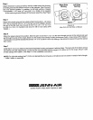
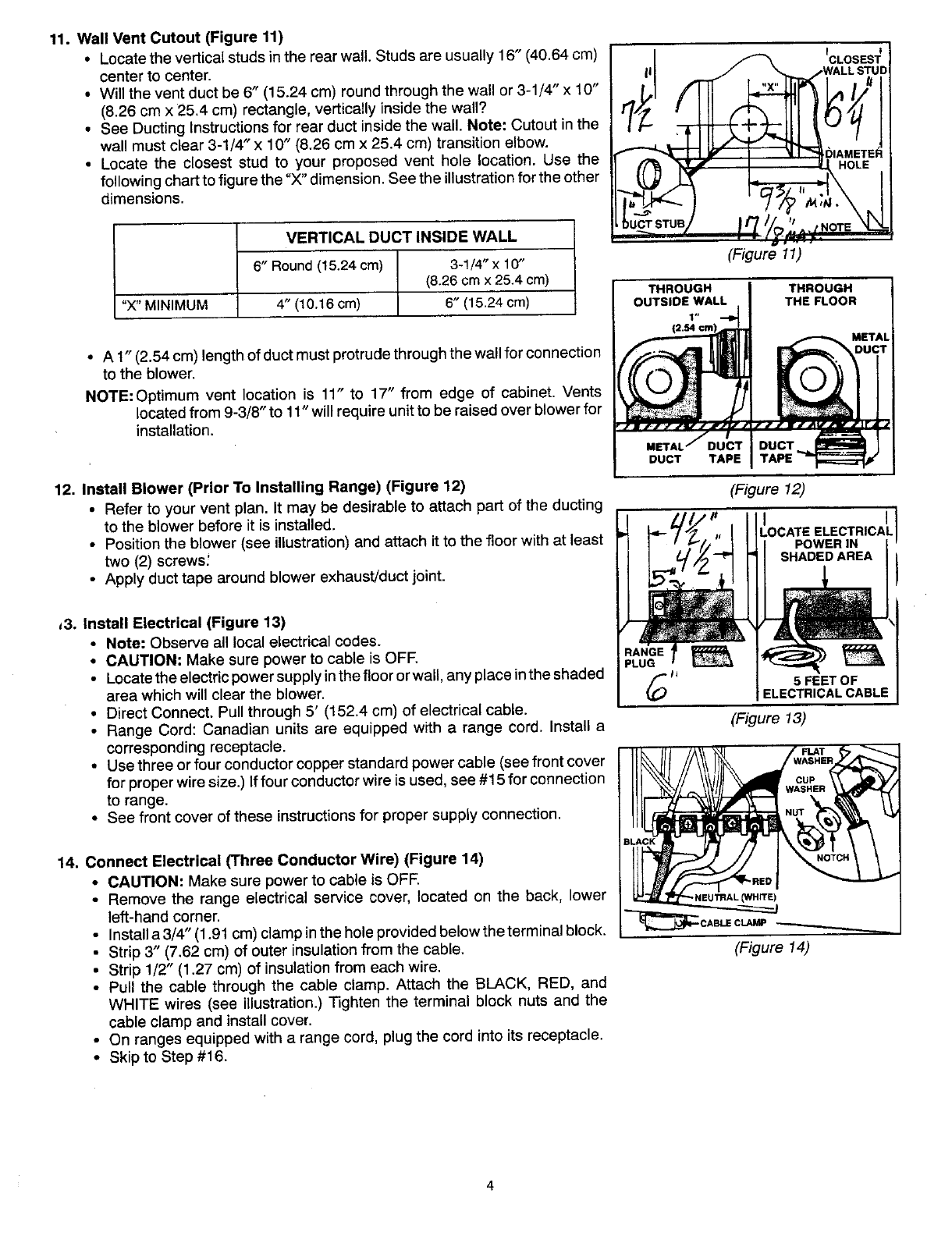
14. ConnectElectrical(ThreeConductorWire)(Figure 14) __o t
• CAUTION:Makesure powerto cable is OFF.
• Remove the range electricalservice cover, located on the back, lower "-NEU'mAL(WHITE)
left-handcorner.
_CABLE CLAMP_
• Installa3/4" (1.91cm)clampintheholeprovidedbelowtheterminalblock. ,
• Strip3" (7.62cm) of outer insulationfrom the cable. (Figure 14)
• Strip1/2" (1.27cm) of insulationfrom eachwire,
• Pull the cable through the cable clamp. Attach the BLACK, RED, and
WHITE wires (see illustration.) Tighten the terminal block nuts and the
cableclamp andinstallcover.
• Onrangesequippedwith a rangecord, plugthe cord into its receptacle.
• Skipto Step #16.