


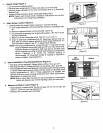
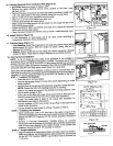
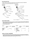
15. ConnectElectrical (Four ConductorWire) (Figure15)
c oo. a esure oweroa.e
• Removethe rangeelectrical servicecover, located on the back, lower _ ;'_
left-handcorner.
• Removethe grounstrapscrewandbendthe strapup as shown.Installa 3/4"
(1.91cm) cable clampin the hole provided,belowthe terminalblock. I,_NOl
• Strip3" (7.62cm) of outer insulationfrom the cable. ,GROUND
• Strip 1/2" (1,27cm)of insulationfrom each wire. WIRE
• Pullthe cablethroughthe cableclamp.
• Makealoopinthe bare groundwire andattachitto the rangewiththe screw "BASe
that heldthe ground strap, _. _'OROUNC)wlSE
• Attach the BLACK,RED,and WHITEwires (see#14.) Tightenthe terminal
block nuts andthe cable clamp. (Figure 15)
• Tapethe ground strap to theWHITE wire as shown.Install electricalcover.
16. Install Options (Figure 16)
• If the backsplash or side panels are to be used, install according to
instructionsincluded inthose accessories.
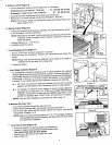
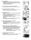
17. PositionRange(Figure 17)
• Free-Standing,Adjustthe rangefeetsothe rangeandcabinetheightwill be
approximately the same. Slide the range into place, taking care not to --
damagefloor covering. . J'
• Slide-In. Adjust range feet so that range top clears countertop. Slide/lift " /
1"
range into place.Adjustfeet so rangeis adjacentto countertop surface. 4 I
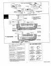
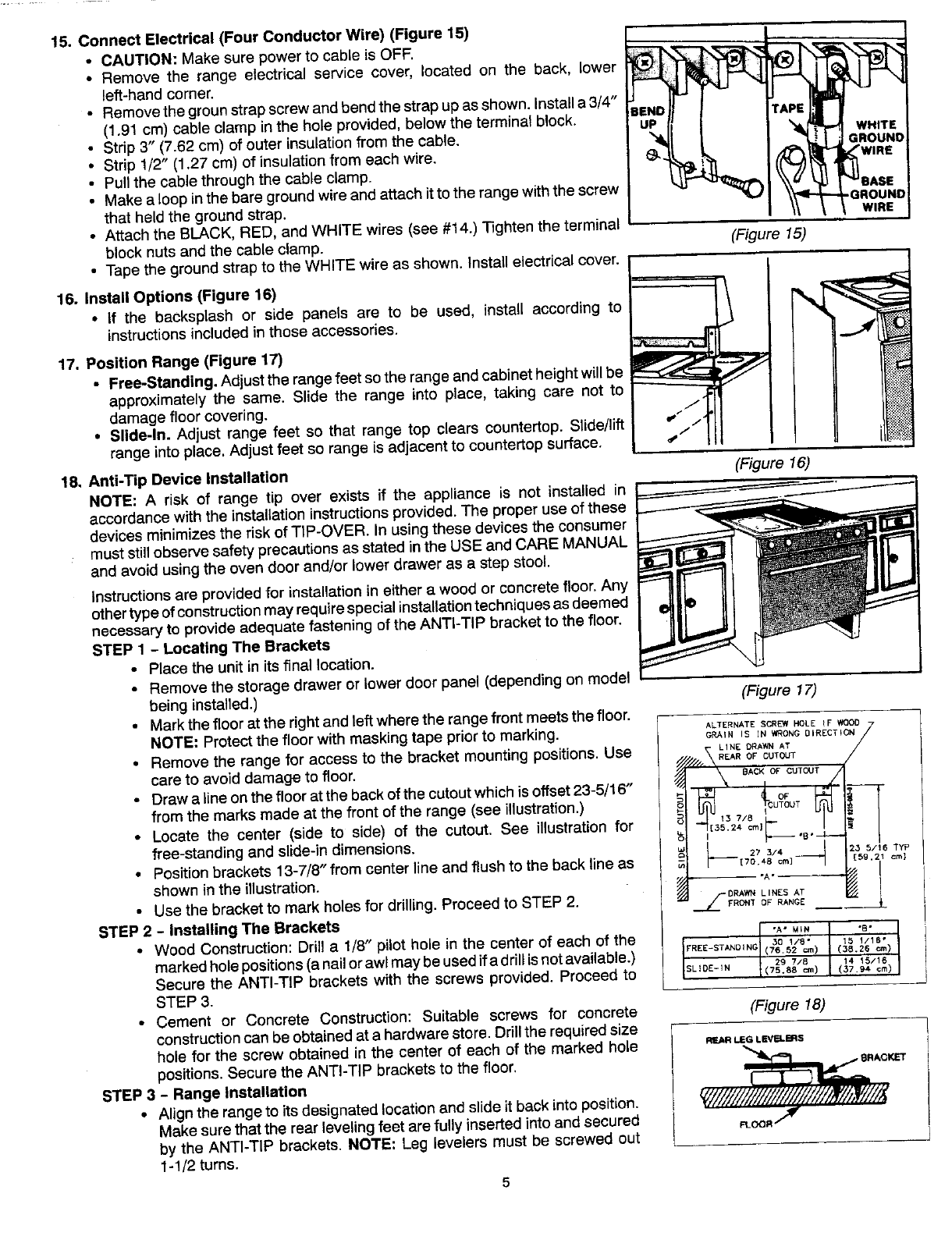
18, Anti-Tip DeviceInstallation (Figure16)
NOTE: A risk of range tip over exists if the appliance is not installed in
accordancewith the installationinstructionsprovided.The proper use ofthese
devicesminimizesthe risk of TIP-OVER.In usingthese devices the consumer
muststillobservesafetyprecautionsas statedin the USE andCAREMANUAL
andavoid usingthe oven door and/or lowerdrawer as a step stool.
Instructionsare providedfor installationin eithera wood or concretefloor.Any
othertypeofconstructionmayrequirespecialinstallationtechniquesas deemed
necessaryto provideadequatefastening of the ANTI-TIPbracketto the floor.
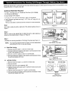
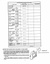
STEP 1 - LocatingThe Brackets
• Placethe unitin itsfinal location.
• Removethe storagedrawer or lowerdoor panel(dependingon model
beinginstalled.) (Figure 17)
• Markthe floorat the right andleftwherethe rangefront meetsthe floor.
NOTE: Protectthe floor with maskingtape prior to marking.
• Removethe rangefor access to the bracket mountingpositions.Use
careto avoid damageto floor.
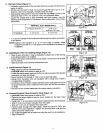
• Drawalineon thefloor at the backof thecutoutwhich isoffset 23-5/16"
from the marks made at the front of the range (see illustration.) _1
,5,1
• Locate the center (side to side) of the cutout. See illustration for
free-standingand slide-indimensions.
Positionbrackets 13-7/8"from centerline andflushto thebackline as _1 2_5/16TYP
• = [59.21 cm]
shown in the illustration.
• Usethe bracketto mark holes for drilling.Proceedto STEP 2. _ _'F.o._0RAw_0_L'NES.AN_EAT
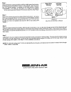
STEP2 - InstallingThe Brackets I
I .A-_L. (_8"2_'=.>
• Wood Construction:Drill a I/8" pilot hole in the center of each of the SL_E-_N _01/_" [5 _/_6"
markedholepositions(anailorawlmaybeusedif adrilJisnotavailable.) F"_E-STAN0_(_6S2=,)
2g 7/8
Securethe ANTI-TIP brackets with the screws provided. Proceed to 1(75.8s_) (379__s/_S.m)_1 II
STEP3.
• Cement or Concrete Construction: Suitable screws for concrete (Figure 18)
constructioncan beobtainedat a hardwarestore.Drillthe requiredsize
hole for the screw obtained in the center of each of the marked hole _._,-e._v_.ms
positions.SecuretheANTI-TIPbracketsto the floor, _ .._OKEr
STEP3- RangeInstallation __/_. - -
• Alignthe range to its designatedlocationandslideitbackinto position.
Make surethat the rearlevelingfeet arefully insertedinto andsecured ___._"
by the ANTI-TIP brackets.NOTE: Leg levelers must be screwed out
1-1/2turns.
5