


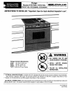

_peCial Instructi---onsFor Ven_net Toe S )ace
Additional instructionsfor ventingthroughthe base cabinettoe space oneithersideof the rangewhen it isnot possibleto vent
throughthe floor or througha rear wall.
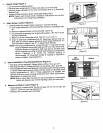
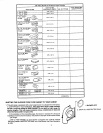
Additional MaterialsRequired
1.5" Dia.x 19" long (12.7cm x 48.26 cm) Flex Duct* (P/N702935) _ "
1 6" (15.24 cm)90° Elbow Left 31.19" Right
• Cabinet 79.22_ Cabinet
2. HoseClamps*(P/N702331)
!
1 5" to 3-1/4" x 10" (12.7cm to 8.26 cmx 25.4 cm)Transition* _-17.12S",-_ _-17.125"-,_
• 5._o' I (_'_ cm) (43.49_) I 5.so'
2. Wood Spacers (rightsidevent only) 1-1/2" Thick x 9" Long (3.81cm Dis-Hole| ' | Dis.Hole
X22.86cm) (,3.,7._. ._..9, or,,
*Seeyourlocaldealerorauthorizedservicecontractorfortheseaccessories. =']-.C-"-_-----"--"- '_ ---------_'---_r =
// -- //
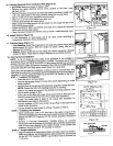
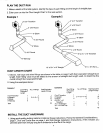
Step 1
Cut a hole in either the left or rightside of the cabinet wall as shown in (Figure 1)
Figure1.
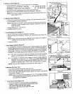
Step2 "h J,.
Make a cutout in the cabinet floor of either the left or right cabinet as _r__ .---t.-
shownbythe shadedareas in Figure 2 or Figure 3. t=7
.===.J==_
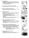
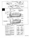
Step3 I'_'_(e=.7_m)=! _o_OT_o"N
_elocatethe mountngbracketson the blowerhousing(see Figure4.)
(Figure2)
NOTE: The mountingbracketshown in Figure 4 are as asssembled Left Cabinet(TopView)
at the factory for flooror rearwall venting.
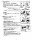
A. RightSide Venting ..¢ iNu='-rltd. _ 14.
2. Removebracketandreattachitwithstuds 1and2 insertedinholes 11"
A and C and replaceall 3 nuts.
3. Remove nutsfrom studs 5, 6 and7 on air inlet side• =
4. Removebracketandreattachitwithstuds5and6insertedinholes s,owe, I- (_o=_7"-m)----'_
D and B and replaceall 3 nuts. ,OCt'nON
(Figure3)
B. Left SideVenting Right Cabinet (TopView)
1. Removenutsfromstuds 1,2, 3 and 4 on motorside. Motor Side Air Inlet Side
2. Removebracket.
....
4. Reattachbracketwithstuds4 and1 insertedinholesA andC and
replaceall 4 nuts.
5. Removenutsfrom studs 5, 6, 7and 8 on air inlet side.
6. Removebracketandreattachitwithstuds8and 5insertedinholes Mounting
D and B and replaceall4 nuts. srecket
(Figure4)
BlowerAssembly